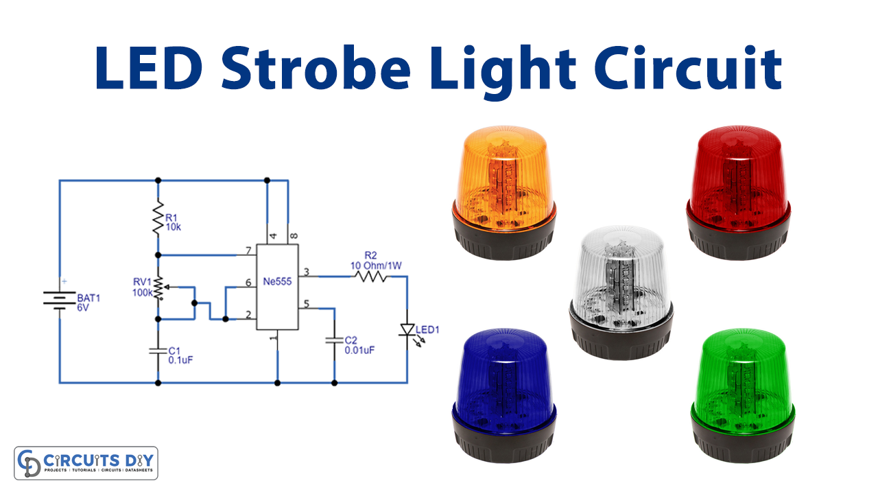
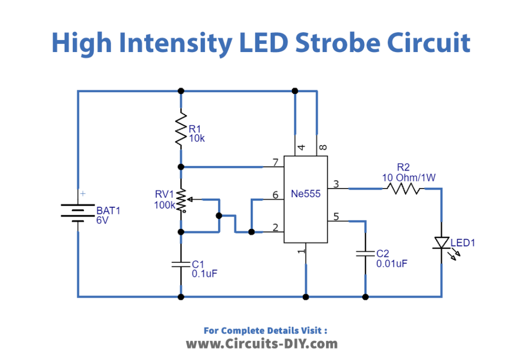
In this tutorial, we are going to make a “High Intensity LED Strobe Circuit”.
A strobe light or a stroboscopic lamp can produce regular flashes of light, it may produce pulses of high-intensity illumination at very high frequencies and very short pulse lengths, which is ideal for high-speed cameras. The LED is off most of the time, so it is not consuming a lot of power or creating a lot of heat. Limiting the duty cycle also lowers the perceived brightness of humans and animals. Here we design a high-intensity LED strobe circuit with timer IC 555 and a few external components. We have used timer IC 555, it is configured as an astable multivibrator and will produce a continuous square pulse depending on the timing resistor and timing capacitor value and 1-watt white LED to produce high-intensity light.

Hardware Components
The following components are required to make LED Strobe Circuit
| S.no | Component | Value | Qty |
|---|---|---|---|
| 1. | IC | NE555 Timer | 1 |
| 2. | Variable Resistor | 100KΩ | 1 |
| 3. | Resistor | 10KΩ, 10Ω/1w | 1,1 |
| 4. | Capacitor | 0.1µF, 0.01µF | 1,1 |
| 5. | LED | 1W | 1 |
| 6. | Connecting Wires | – | 1 |
| 7. | Battery | 6V | 1 |
555 IC Pinout

For a detailed description of pinout, dimension features, and specifications download the datasheet of 555 Timer
LED Strobe Circuit
Working Explanation
To construct this circuit, we need a timer IC 555 and timing elements resistor R1, capacitor C1, and variable resistor RV1. Here timer ICs ’ Pin 8 and 4 are connected to the positive terminal of the battery and pin 1 to the negative supply, pin 5 is connected with the negative supply through capacitor 2. Resistor R1, RV1, and Capacitor C1 are connected serially and between Discharge pin 7, threshold pin 6, and trigger pin 2. Output pin 3 from timer IC 555 is connected with a 1-Watt white LED through the R2 resistor. The main part of the circuit is the 555 which is operating in an astable multivibrator.
The 555 Timer can operate in 3 different modes such as astable, monostable, and bistable mode. All these three modes produce three different types of pulses which can be controlled at a particular point. ON and OFF square pulse generated by the timer IC 555 depending on the timing elements value. Now that the output from pin 3 is applied to the white led, the LED starts to blink according to the ON and OFF pulses. This delay can be controlled by changing the values of the resistor R1, variable resistor RV1, and capacitor C2. The formula to calculate the delay is shown below.
Output Time (T) = 0.693(R1 + 2RV1).C
RV1 = Current position resistance value (because it’s a variable resistor) and not the whole RV1 resistance value.
Applications
Can be used in high-speed cameras.