
Related Manuals for Genius SW-HF 5.1 6000


Summary of Contents for Genius SW-HF 5.1 6000
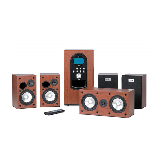
- Page 1 Service Guide SW-HF 5.1 6000 SERVICE GUIDE KYE SYSTEM CORP Version 1.0 Page 1 of 36...
-
Page 2: Revision History
Service Guide SW-HF 5.1 6000 Revision History Version Date Change 26/03/2008 Version 1.0 Page 2 of 36... -
Page 3: Table Of Contents
Chapter 5. Part list…………………………………… …………….…………...23 Woofer………………………………………………………….………………..23 Center/Front/Rear………………………………………………………………24 Chapter 6 Important notes……………………………………………………….25 Chapter 7 Circuit diagram………………………………………………………..26 SW-HF 5.1 6000 INPUT PCB……………………………………….……..26 SW-HF 5.1 6000 CON PCB…………………………………………..…..…..27 SW-HF 5.1 AMP PCB …………………….………….…………………..…...28 SW-HF 5.1 SWAMP PCB……………………….………………… ..………..29 SW-HF 5.1 REM PCB………………………………..…………….…..……30 Chapter 8 PCBA……………………………………………………………….……..31 SW-HF 5.1 6000 INPUT PCBA………………………………………………31... -
Page 4: Getting Start
Service Guide SW-HF 5.1 6000 Getting Started Conventions Used in the Guide Pay Special Attention: Instructions that are important to remember and may prevent mistakes. Caution: Information that, if not followed, may result in damage to the product. Safety Precautions... -
Page 5: Chapter 1. How To Handle Defective Returns
Service Guide SW-HF 5.1 6000 Chapter 1. How to Handle Defective Returns 1.1 Overview Receiving Defective speaker from customers Verifying problems Proceeding Necessary tests Function NG Function OK Function NG Analyzing possible Malfunction cause Deciding & proceeding the Rectification methods... -
Page 6: Problem
Service Guide SW-HF 5.1 6000 1.2 Problems Item Problem Description 1.2.1 No power,LCD no light 1.2.2 No sound 1.2.3 Front channel no sound (including either FR or FL no sound) 1.2.4 Rear channel no sound (including either RR or RL no sound) 1.2.5... -
Page 7: No Power, Lcd No Light
Service Guide SW-HF 5.1 6000 *Attention Please follow the numbered sequence marked within parenthesis given in individual Flow chat in that this is the best-recommended sequence to rectify the problems. 1.2.1 No power,LCD unlighted No power, LCD no light Problem Analyze 1. -
Page 8: No Sound
Service Guide SW-HF 5.1 6000 1.2.2 no sound No sound Problem CON PCB PCB broken, Assembled line 1. Defective IC2 on INPUT PCB dry-soldered or defectively 2. Defective IC1, IC2 on Analyze and short-circuited connected 3. Defective IC1, IC2, IC3, IC4, IC5, IC6, IC7, IC8, IC9, R28,... -
Page 9: Front Channel No Sound (Including Either Fr Or Fl No Sound)
Service Guide SW-HF 5.1 6000 Front channel no sound (including either FR or FL no sound ) 1.2.3 Front channel no sound (including either FR or FL no sound) Problem 1.defective IC1, PCB damaged, Poor connection of Defective components relating to IC1 and... -
Page 10: Rear Channel No Sound (Including Either Rr Or Rl No Sound)
Service Guide SW-HF 5.1 6000 1.2.4 Rear channel no sound (including either RR or RL no sound) Problem or RL no sound) Rear channel no sound (including either RR Defective damaged, Poor connection of 1. Defective IC1, IC2 or other... -
Page 11: Center No Sound
Service Guide SW-HF 5.1 6000 1.2.5 Center no sound Problem Center no sound Poor soldering, Poor connection Defective Defective IC1, Analyze and broken, or short center connection components relating to IC1 identify the circuit PCB speaker cables center audio and IC2 on INPUT PCB... -
Page 12: Woofer No Sound
Service Guide SW-HF 5.1 6000 1.2.6 Woofer no sound Problem Woofer no sound 1. Defective IC1, IC2 or Poor connection Defective Power-supply Analyze and components relating to IC1 of sub speaker connection part dry-soldered, identify the and IC2 on INPUT PCB... -
Page 13: Input No Sound
Service Guide SW-HF 5.1 6000 1.2.7 input no sound Problem input no sound Defective INPUT PCB soldering Defective input Analyze and components relating to points broken, RCA jack identify the inputs on INPUT PCB soldered short causes -circuited Check Check... -
Page 14: Remote Control No Use
Service Guide SW-HF 5.1 6000 1.2.8 Remote control no use Problem Remote control no use Defective IR1, IC3, R1, Defective Low power of Defective broken, or its EC1, CC1 on CON soldering the battery conductive Analyze and other battery spring... -
Page 15: Noise
Service Guide SW-HF 5.1 6000 1.2.9. Noise Problem Noise Defective Broken or dry-soldered Abnormal power Vibration from too long dry-soldered filter capacitor/ diode supply or point flexible wire of the driver Analyze and components voltage of some units identify the... -
Page 16: Lcd Malfunction
Service Guide SW-HF 5.1 6000 1.2.10. LCD malfunction Problem LCD malfunction LCD improper or no display: CON PCB defective , dry-soldered, LCD text not clear: Analyze and or broken CON PCB defective , dry-soldered, or broken identify the LCD1, IC1 on CON PCB defective... -
Page 17: Chapter 2. Specification
Service Guide SW-HF 5.1 6000 Chapter 2. Specifications Satellite DESCRIPTION UNIT NOMINAL LIMIT ≧20 1 RATED OUTPUT POWER @THD 10% 2 SENSITIVITY (1KHz) @RATED O/P POWER ±10% 3 SENSITIVITY (1KHz) @1W O/P POWER ±10% 4 MAX INPUT LEVEL@1% THD ±10% 5 FREQUENCY RESPONSE(1KHz -3DB ) LOW ±20... -
Page 18: Woofer
Service Guide SW-HF 5.1 500 Chapter 2 Specifications Woofer DESCRIPTION UNIT NOMINAL LIMIT ≧100 1 RATED OUTPUT POWER@100Hz(10%THD) 2 SENSITVITY(100Hz)@RATED O/P POWER ±10 3 SENSITIVITY(100Hz)@1W O/P POWER ±3.8 4 MAX INPUT LEVEL@1% THD ±9.5 ≦0.5 DISTORTION@100Hz REF O/P POWER 6 FREQUENCY RESPONSE (100Hz -3DB)LOW ±10 7 FREQUENCY RESPONSE (100Hz -3DB)HI ±20... -
Page 19: Chapter 3 Block Diagram
Service Guide SW-HF 5.1 6000 Chapter 3 Block diagram Version 1.0 Page 19 of 36... -
Page 20: Chapter 4 Exploded View
Service Guide SW-HF 5.6000 Chapter 4 Exploded view Subwoofer Version 1.0 Page 20 of 36... -
Page 21: Satellite (Center)
Service Guide SW-HF 5.1 6000 Chapter 4 Exploded view Satellite (Center) Version 1.0 Page 21 of 36... -
Page 22: Satellite (Front/Rear)
Service Guide SW-HF 5.1 6000 Chapter 4 Exploded view Satellite (Front/Rear) Front Rear Version 1.0 Page 22 of 36... -
Page 23: Chapter 5 Part List
Service Guide SW-HF 5.1 6000 Chapter 5 Part list Woofer Ref. NO Description Part NO. master volume knob φ38*23 EP40758018 silver keystroke EP40714169A LCD cover, ABS EP40810052 front panel EP40310321 transparent cover for IR receiver EP41410034 EP1B020070 LCD panel EP1D010029 SW-HF5.1 6000 CON94HB PCB, 176*84*1.6MM... -
Page 24: Center/Front/Rear
Service Guide SW-HF 5.1 6000 Chapter 5 Part list Center Ref. NO Description Part NO. Genius LOGO plate: M72 60*23*2MM EP75050198 cloth and cloth grill EP41010156 center driver unit, A-115-9, 4"Ω420W EP16040012 tweeter, A-52-2A, 2"8Ω10W EP16020043 center wood cabinet, W331.5*H160*D130MM... -
Page 25: Chapter 6 Important Notes
Service Guide SW-HF 5.1 6000 Chapter 6. Important Notes 6.1 Packing requirement for sending the PCB assembly by post PCB assembly is a kind of sophisticated electronic circuit board. Well packing will be required when sending them by post. *Some sophisticated IC components are mounted on the PCB assembly;... -
Page 26: Chapter 7 Circuit Diagram
Service Guide SW-HF 5.1 6000 Chapter 7. Schematic diagram SW-HF 5.1 6000 INPUT PCB Version 1.0 Page 26 of 36... -
Page 27: Sw-Hf 5.1 6000 Con Pcb
Service Guide SW-HF 5.1 6000 Chapter 7. Schematic diagram SW-HF 5.1 6000 CON PCB Version 1.0 Page 27 of 36... -
Page 28: Sw-Hf5.1 Amp Pcb
Service Guide SW-HF 5.1 6000 Chapter 7. Schematic diagram SW-HF5.1 AMP PCB Version 1.0 Page 28 of 36... -
Page 29: Sw-Hf 5.1 Swamp Pcb
Service Guide SW-HF 5.1 6000 Chapter 7. Schematic diagram SW-HF 5.1 SWAMP & SATSP PCB Version 1.0 Page 29 of 36... -
Page 30: Sw-Hf 5.1 Rem Pcb
Service Guide SW-HF 5.1 6000 Chapter 7. Schematic diagram SW-HF5.1 REM PCB (remote control) Version 1.0 Page 30 of 36... -
Page 31: Chapter 8 Pcba
Service Guide SW-HF 5.1 6000 Chapter 8. PCBA picture SW-HF 5.1 6000 INPUT PCB Version 1.0 Page 31 of 36... -
Page 32: Sw-Hf 5.1 6000 Con Pcba
Service Guide SW-HF 5.1 6000 Chapter 8. PCBA picture SW-HF5.1 6000 CON PCB Version 1.0 Page 32 of 36... -
Page 33: Sw-Hf5.1 Amp Pcba
Service Guide SW-HF 5.1 6000 Chapter 8. PCBA picture SW-HF5.1 AMP PCBA Version 1.0 Page 33 of 36... -
Page 34: Sw-Hf5.1 Swamp Pcba
Service Guide SW-HF 5.1 6000 Chapter 8. PCBA picture SW-HF5.1 SWAMP PCBA Version 1.0 Page 34 of 36... -
Page 35: Sw-Hf5.1 Satsp Pcba
Service Guide SW-HF 5.1 6000 Chapter 8. PCBA picture SW-HF5.1 SATSP PCBA Version 1.0 Page 35 of 36... -
Page 36: Sw-Hf5.1 Rem Pcba
Service Guide SW-HF 5.1 6000 Chapter 8. PCBA picture SW-HF5.1 REM PCBA Version 1.0 Page 36 of 36...