Abit Fatal1ty AN9 32X Manual - TigerDirect.com
Abit Fatal1ty AN9 32X Manual - TigerDirect.com
Abit Fatal1ty AN9 32X Manual - TigerDirect.com

Create successful ePaper yourself
Turn your PDF publications into a flip-book with our unique Google optimized e-Paper software.
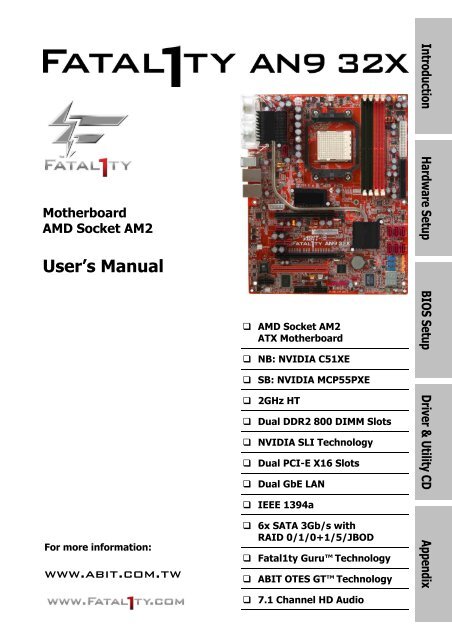
Motherboard<br />
AMD Socket AM2<br />
User’s <strong>Manual</strong><br />
For more information:<br />
www.abit.<strong>com</strong>.tw<br />
AMD Socket AM2<br />
ATX Motherboard<br />
NB: NVIDIA C51XE<br />
SB: NVIDIA MCP55PXE<br />
2GHz HT<br />
Dual DDR2 800 DIMM Slots<br />
NVIDIA SLI Technology<br />
Dual PCI-E X16 Slots<br />
Dual GbE LAN<br />
IEEE 1394a<br />
6x SATA 3Gb/s with<br />
RAID 0/1/0+1/5/JBOD<br />
<strong>Fatal1ty</strong> Guru Technology<br />
ABIT OTES GT Technology<br />
7.1 Channel HD Audio<br />
Introduction<br />
Hardware Setup BIOS Setup Driver & Utility CD Appendix
ii<br />
User’s <strong>Manual</strong><br />
English, 1 st Edition<br />
May, 2006<br />
Copyright and Warranty Notice<br />
The information in this document is subject to change without notice and does not represent a<br />
<strong>com</strong>mitment on part of the vendor, who assumes no liability or responsibility for any errors that may<br />
appear in this manual.<br />
No warranty or representation, either expressed or implied, is made with respect to the quality,<br />
accuracy or fitness for any particular part of this document. In no event shall the manufacturer be<br />
liable for direct, indirect, special, incidental or consequential damages arising from any defect or<br />
error in this manual or product.<br />
Product names appearing in this manual are for identification purpose only and trademarks and<br />
product names or brand names appearing in this document are the property of their respective<br />
owners.<br />
This document contains materials protected under International Copyright Laws. All rights reserved.<br />
No part of this manual may be reproduced, transmitted or transcribed without the expressed written<br />
permission of the manufacturer and authors of this manual.<br />
If you do not properly set the motherboard settings, causing the motherboard to malfunction or fail,<br />
we cannot guarantee any responsibility.<br />
The <strong>Fatal1ty</strong> name, <strong>Fatal1ty</strong> logos and the <strong>Fatal1ty</strong> likeness are trademarks of <strong>Fatal1ty</strong>,<br />
Inc. All rights reserved. Built to Kill is a trademark of PWX, LLC.<br />
© 2006 UNIVERSAL ABIT Co., Ltd.<br />
All other trademarks are the property of their respective owners.
Contents<br />
1. Introduction..................................................................... 1-1<br />
1.1 <strong>Fatal1ty</strong> ......................................................................................1-1<br />
1.2 Features & Specifications .............................................................1-3<br />
1.3 Motherboard Layout.....................................................................1-5<br />
2. Hardware Setup ............................................................... 2-1<br />
2.1 Choosing a Computer Chassis.......................................................2-1<br />
2.2 Installing Motherboard .................................................................2-1<br />
2.3 Checking Jumper Settings ............................................................2-2<br />
2.3.1 CMOS Memory Clearing Header and Backup Battery ..............2-3<br />
2.3.2 Wake-up Headers................................................................2-5<br />
2.4 Connecting Chassis Components...................................................2-6<br />
2.4.1 ATX Power Connectors ........................................................2-6<br />
2.4.2 Front Panel Switches & Indicators Headers............................2-7<br />
2.4.3 FAN Power Connectors ........................................................2-8<br />
2.5 Installing Hardware......................................................................2-9<br />
2.5.1 CPU Socket AM2 .................................................................2-9<br />
2.5.2 DDR2 Memory Slots ..........................................................2-11<br />
2.5.3 PCI Express X16 Add-on Slots (Install Graphics Card) ..........2-13<br />
2.5.4 AudioMAX Connection Slot .................................................2-16<br />
2.6 Connecting Peripheral Devices ....................................................2-19<br />
2.6.1 Floppy and IDE Disk Drive Connectors ................................2-19<br />
2.6.2 Serial ATA Connectors .......................................................2-20<br />
2.6.3 Additional USB 2.0 Port Headers.........................................2-21<br />
2.6.4 Additional IEEE1394 Port Headers ......................................2-22<br />
2.6.5 PCI Express X1 Add-on Slots ..............................................2-23<br />
2.6.6 PCI Add-on Slots ...............................................................2-23<br />
2.6.7 GURU Panel Connection Header .........................................2-24<br />
2.7 Onboard Status Display..............................................................2-25<br />
2.7.1 POST Code Displayer.........................................................2-25<br />
2.7.2 Power Source Indicators ....................................................2-26<br />
2.8 Connecting I/O Devices..............................................................2-27<br />
3. BIOS Setup....................................................................... 3-1<br />
3.1 µGuru Utility..............................................................................3-2<br />
3.1.1 OC Guru .............................................................................3-2<br />
3.1.2 ABIT EQ .............................................................................3-2<br />
iii<br />
Introduction<br />
Hardware Setup BIOS Setup Driver & Utility CD Appendix
iv<br />
3.2 Standard CMOS Features..............................................................3-3<br />
3.3 Advanced BIOS Features ..............................................................3-3<br />
3.4 Advanced Chipset Features...........................................................3-4<br />
3.5 Integrated Peripherals..................................................................3-4<br />
3.6 Power Management Setup............................................................3-5<br />
3.7 PnP/PCI Configurations ................................................................3-5<br />
3.8 Load Fail-Safe Defaults ................................................................3-6<br />
3.9 Load Optimized Defaults ..............................................................3-6<br />
3.10 Set Password.............................................................................3-6<br />
3.11 Save & Exit Setup ......................................................................3-6<br />
3.12 Exit Without Saving....................................................................3-6<br />
4. Driver & Utility CD............................................................ 4-1<br />
5. Appendix .......................................................................... 5-1<br />
5.1 POST Code Definitions .................................................................5-1<br />
5.1.1 AWARD POST Code Definitions.............................................5-1<br />
5.1.2 AC2005 POST Code Definitions.............................................5-4<br />
5.2 Troubleshooting (How to Get Technical Support?)..........................5-5<br />
5.2.1 Q & A.................................................................................5-5<br />
5.2.2 Technical Support Form ......................................................5-8<br />
5.2.3 UNIVERSAL ABIT Contact Information ..................................5-9
1. Introduction<br />
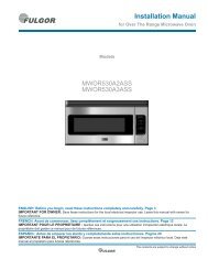
1.1 <strong>Fatal1ty</strong><br />
FATAL1TY STORY<br />
Who knew that at age 19, I would be<br />
a World Champion PC gamer. When<br />
I was 13, I actually played<br />
<strong>com</strong>petitive billiards in professional<br />
tournaments and won four or five<br />
games off guys who played at the<br />
highest level. I actually thought of<br />
making a career of it, but at that<br />
young age situations change rapidly.<br />
Because I’ve been blessed with great<br />
hand-eye coordination and a grasp of<br />
mathematics (an important element<br />
in video gaming) I gravitated to that<br />
activity.<br />
GOING PRO<br />
I started professional gaming in 1999 when I entered the CPL (Cyberathlete Professional<br />
League) tournament in Dallas and won $4,000 for <strong>com</strong>ing in third place. Emerging as one of<br />
the top players in the United States, a <strong>com</strong>pany interested in sponsoring me flew me to Sweden<br />
to <strong>com</strong>pete against the top 12 players in the world. I won 18 straight games, lost none, and<br />
took first place, be<strong>com</strong>ing the number one ranked Quake III player in the world in the process.<br />
Two months later I followed that success by traveling to Dallas and defending my title as the<br />
world’s best Quake III player, winning the $40,000 grand prize. My earned frags allowed at<br />
this tournament were 2.5. From there I entered <strong>com</strong>petitions all over the world, including<br />
Singapore, Korea, Germany, Australia, Holland and Brazil in addition to Los Angeles, New York<br />
and St. Louis.<br />
WINNING STREAK<br />
I was excited to showcase my true gaming skills when defending my title as CPL Champion of<br />
the year at the CPL Winter 2001 because I would be <strong>com</strong>peting in a totally different first person<br />
shooter (fps) game, Alien vs. Predator II. I won that <strong>com</strong>petition and walked away with a new<br />
car. The next year I won the same title playing Unreal Tournament 2003, be<strong>com</strong>ing the only<br />
three-time CPL champion. And I did it playing a different game each year, something no one<br />
else has ever done and a feat of which I am extremely proud.<br />
At QuakeCon 2002, I faced off against my rival ZeRo4 in one of the most highly anticipated<br />
matches of the year, winning in a 14 to (-1) killer victory. Competing at Quakecon 2004, I<br />
became the World’s 1 st Doom3 Champion by defeating Daler in a series of very challenging<br />
matches and earning $25,000 for the victory.<br />
1-1<br />
Introduction
LIVIN’ LARGE<br />
Since my first big tournament wins, I have been a “Professional Cyberathlete”, traveling the<br />
world and livin’ large with lots of International media coverage on outlets such as MTV, ESPN<br />
and G4TV to name only a few. It's unreal - it's crazy. I’m living a dream by playing video<br />
games for a living. I’ve always been athletic and took sports like hockey and football very<br />
seriously, working out and training hard. This discipline helps me be<strong>com</strong>e a better gamer and<br />
my drive to be the best has opened the doors necessary to be<strong>com</strong>e a professional.<br />
A DREAM<br />
Now, another dream is being realized – building the ultimate gaming <strong>com</strong>puter, made up of the<br />
best parts under my own brand. Quality hardware makes a huge difference in <strong>com</strong>petitions…a<br />
couple more frames per second and everything gets really nice. It's all about getting the<br />
<strong>com</strong>puter processing faster and allowing more fluid movement around the maps.<br />
My vision for <strong>Fatal1ty</strong> hardware is to allow gamers to focus on the game without worrying<br />
about their equipment, something I’ve preached since I began <strong>com</strong>peting. I don’t want to<br />
worry about my equipment. I want it to be there – over and done with - so I can focus on the<br />
game. I want it to be the fastest and most stable <strong>com</strong>puter equipment on the face of the<br />
planet, so quality is what <strong>Fatal1ty</strong> brand products will represent.<br />
FATAL1TY BRAIN TRUST<br />
This is just the beginning. We’re already in development for several new products, and I’m<br />
really grateful to all my <strong>Fatal1ty</strong> Brain Trust partners for helping make my dreams a reality.<br />
I know there is a business side to all of this, but for me the true reward is making products that<br />
are so good I can win with them – and making them available to fellow gamers. Gaming is my<br />
life, and many fellow gamers around the world are also some of my best friends, so giving back<br />
to the gaming <strong>com</strong>munity is really important to me.<br />
Johnathan “<strong>Fatal1ty</strong>” Wendel<br />
1-2
1.2 Features & Specifications<br />
CPU<br />
Supports Socket 940 AM2 Processor with 2GHz system bus using Hyper-Transport<br />
Technology<br />
Supports AMD CPU Cool ‘n’ Quiet Technology<br />
Chipset<br />
Northbridge: NVIDIA ® C51XE Chipset<br />
Southbridge: NVIDIA ® MCP55PXE Chipset<br />
Memory<br />
Four 240-pin DIMM slots<br />
Supports Dual Channel DDR2 800 Un-buffered ECC/Non-ECC memory<br />
Supports maximum memory capacity up to 8GB<br />
ABIT Engineered<br />
ABIT <strong>Fatal1ty</strong> Guru Technology<br />
ABIT OTES GT Technology<br />
NVIDIA SLI Technology<br />
Two PCI-Express X16 slots support NVIDIA Scalable Link Interface<br />
SATA 3Gb/s RAID<br />
Supports 6 ports NV SATA 3Gb/s RAID 0/1/0+1/5/JBOD<br />
Dual GbE LAN<br />
Dual NVIDIA ® Gigabit Ethernet<br />
IEEE 1394<br />
Supports 2 Ports IEEE 1394a at 400Mb/s transfer rate<br />
Audio<br />
ABIT AudioMAX HD 7.1 CH<br />
Supports auto jack sensing and optical S/PDIF In/Out<br />
Expansion Slots<br />
2x PCI Express x16 slots<br />
2x PCI Express x1 slots<br />
1x PCI slot<br />
1x AudioMAX slot<br />
Internal I/O Connectors<br />
1x Floppy port<br />
1x UDMA 133/100/66/33 connector<br />
6x SATA connectors<br />
3x USB 2.0 headers<br />
1-3<br />
Introduction
2x IEEE1394a headers<br />
Rear Panel I/O<br />
OTES GT <br />
1x PS/2 Keyboard connector<br />
1x PS/2 Mouse connector<br />
2x RJ-45 Gigabit LAN ports<br />
4x USB 2.0 ports<br />
Miscellaneous<br />
ATX form factor (305mm x 245mm)<br />
Specifications and information contained herein are subject to change without notice.<br />
For more information:<br />
www.abit.<strong>com</strong>.tw<br />
1-4
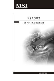
1.3 Motherboard Layout<br />
1-5<br />
Introduction
For more information:<br />
www.abit.<strong>com</strong>.tw<br />
1-6
2. Hardware Setup<br />
In this chapter we will elaborate all the information you need upon installing this motherboard<br />
to your <strong>com</strong>puter system.<br />
※ Always power off the <strong>com</strong>puter and unplug the AC power cord before adding or<br />
removing any peripheral or <strong>com</strong>ponent. Failing to so may cause severe damage<br />
to your motherboard and/or peripherals. Plug in the AC power cord only after<br />
you have carefully checked everything.<br />
2.1 Choosing a Computer Chassis<br />
This motherboard carries an ATX form factor of 305 x 245 mm. Choose a chassis big<br />
enough to install this motherboard.<br />
As some features for this motherboard are implemented by cabling connectors on the<br />
motherboard to indicators and switches or buttons on the chassis, make sure your chassis<br />
supports all the features required.<br />
If there is possibility of adopting some more hard drives, make sure your chassis has<br />
sufficient power and space for them.<br />
Most chassis have alternatives for I/O shield located at the rear panel. Make sure the I/O<br />
shield of the chassis matches the I/O port configuration of this motherboard. You can find<br />
an I/O shield specifically designed for this motherboard in its package.<br />
2.2 Installing Motherboard<br />
Most <strong>com</strong>puter chassis have a base with<br />
many mounting holes to allow the<br />
motherboard to be securely attached, and at<br />
the same time, prevent the system from<br />
short circuits. There are two ways to attach<br />
the motherboard to the chassis base:<br />
1. with studs,<br />
2. or with spacers<br />
In principle, the best way to attach the board<br />
is with studs. Only if you are unable to do<br />
this should you attach the board with spacers.<br />
Line up the holes on the board with the mounting holes on the chassis. If the holes line up and<br />
there are screw holes, you can attach the board with studs. If the holes line up and there are<br />
only slots, you can only attach with spacers. Take the tip of the spacers and insert them into<br />
the slots. After doing this to all the slots, you can slide the board into position aligned with slots.<br />
After the board has been positioned, check to make sure everything is OK before putting the<br />
chassis back on.<br />
2-1<br />
Hardware Setup
To install this motherboard:<br />
1. Locate all the screw holes on<br />
the motherboard and the<br />
chassis base.<br />
2. Place all the studs or spacers<br />
needed on the chassis base<br />
and have them tightened.<br />
3. Face the motherboard’s I/O<br />
ports toward the chassis’s rear<br />
panel.<br />
4. Line up all the motherboard’s<br />
screw holes with those studs or<br />
spacers on the chassis.<br />
5. Install the motherboard with<br />
screws and have them<br />
tightened.<br />
Face the chassis’s rear panel.<br />
※ To prevent shorting the PCB circuit, please REMOVE the metal studs or spacers if<br />
they are already fastened on the chassis base and are without mounting-holes<br />
on the motherboard to align with.<br />
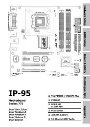
2.3 Checking Jumper Settings<br />
For a 2-pin jumper, plug the jumper cap on both pins will make it CLOSE (SHORT). Remove the<br />
jumper cap, or plug it on either pin (reserved for future use) will leave it at OPEN position.<br />
SHORT OPEN OPEN<br />
For 3-pin jumper, pin 1~2 or pin 2~3 can be shorted by plugging the jumper cap in.<br />
2-2<br />
Pin 1~2 SHORT Pin 2~3 SHORT
2.3.1 CMOS Memory Clearing Header and Backup Battery<br />
The time to clear the CMOS memory occurs when (a) the CMOS data be<strong>com</strong>es corrupted, (b)<br />
you forgot the supervisor or user password preset in the BIOS menu, (c) you are unable to<br />
boot-up the system because the CPU ratio/clock was incorrectly set in the BIOS menu.<br />
This header uses a jumper cap to clear the CMOS memory and have it reconfigured to the<br />
default values stored in BIOS.<br />
Pins 1 and 2 shorted (default): Normal operation.<br />
Pins 2 and 3 shorted: Clear CMOS memory.<br />
To clear the CMOS memory and load in the default values:<br />
1. Power off the system and disconnect with AC power source.<br />
2. Set pin 2 and pin 3 shorted by the jumper cap. Wait for a few seconds. Set the jumper cap<br />
back to its default settings --- pin 1 and pin 2 shorted.<br />
3. Power on the system.<br />
4. For incorrect CPU ratio/clock settings in the BIOS, press key to enter the BIOS setup<br />
menu right after powering on system.<br />
5. Set the CPU operating speed back to its default or an appropriate value.<br />
6. Save and exit the BIOS setup menu.<br />
2-3<br />
Hardware Setup
CMOS Backup Battery:<br />
An onboard battery saves the CMOS memory to keep the BIOS information stays on even after<br />
disconnected your system with power source. Nevertheless, this backup battery exhausts after<br />
some five years. Once the error message like “CMOS BATTERY HAS FAILED” or “CMOS<br />
checksum error” displays on monitor, this backup battery is no longer functional and has to<br />
be renewed.<br />
To renew the backup battery:<br />
1. Power off the system and disconnect with AC power source.<br />
2. Remove the exhausted battery.<br />
3. Insert a new CR2032 or equivalent battery. Pay attention to its polarity. The “+” side is its<br />
positive polarity.<br />
4. Connect AC power source and power on the system.<br />
5. Enter the BIOS setup menu. Reconfigure the setup parameters if necessary.<br />
CAUTION:<br />
※ Danger of explosion may arise if the battery is incorrectly renewed.<br />
※ Renew only with the same or equivalent type re<strong>com</strong>mended by the battery<br />
manufacturer.<br />
※ Dispose of used batteries according to the battery manufacturer’s instructions.<br />
2-4
2.3.2 Wake-up Headers<br />
These headers use a jumper cap to enable/disable the wake-up function.<br />
PS2-PWR1:<br />
Pin 1-2 shorted (Default): Disable wake-up function support at Keyboard/Mouse port.<br />
Pin 2-3 shorted: Enable wake-up function support at Keyboard/Mouse port.<br />
USB-PWR1:<br />
Pin 1-2 shorted (Default): Disable wake-up function support at USB1 port.<br />
Pin 2-3 shorted: Enable wake-up function support at USB1 port.<br />
USB-PWR2:<br />
Pin 1-2 shorted (Default): Disable wake-up function support at USB2 port.<br />
Pin 2-3 shorted: Enable wake-up function support at USB2 port<br />
FP-PWR1:<br />
Pin 1-2 shorted (Default): Disable wake-up function support at FP-USB1 port.<br />
Pin 2-3 shorted: Enable wake-up function support at FP-USB1 port.<br />
FP-PWR2:<br />
Pin 1-2 shorted (Default): Disable wake-up function support at FP-USB2 port.<br />
Pin 2-3 shorted: Enable wake-up function support at FP-USB2 port<br />
FP-PWR3:<br />
Pin 1-2 shorted (Default): Disable wake-up function support at FP-USB3 port.<br />
Pin 2-3 shorted: Enable wake-up function support at FP-USB3 port<br />
2-5<br />
Hardware Setup
2.4 Connecting Chassis Components<br />
2.4.1 ATX Power Connectors<br />
These connectors provide the connection from an ATX power supply. As the plugs from the<br />
power supply fit in only one orientation, find the correct one and push firmly down into these<br />
connectors.<br />
ATX 24-Pin Power Connector:<br />
The power supply with 20-pin or 24-pin cables can both be connected to this 24-pin connector.<br />
Connect from pin-1 for either type. However, a 20-pin power supply may cause the system<br />
unstable or even unbootable for the sake of insufficient electricity. A minimum power of 300W<br />
or higher is re<strong>com</strong>mended.<br />
ATX 12V 4-Pin Power Connector:<br />
This connector supplies power to CPU. The system will not start without connecting power to<br />
this one.<br />
Auxiliary 12V Power Connector:<br />
2-6<br />
This connector provides an auxiliary power source for devices added on PCI<br />
Express slots.
2.4.2 Front Panel Switches & Indicators Headers<br />
This header is used for connecting switches and LED indicators on the chassis front panel.<br />
Watch the power LED pin position and orientation. The mark “+” align to the pin in the figure<br />
below stands for positive polarity for the LED connection. Please pay attention to connect these<br />
headers. A wrong orientation will only cause the LED not lighting, but a wrong connection of<br />
the switches could cause system malfunction.<br />
HLED (Pin 1, 3):<br />
Connects to the HDD LED cable of chassis front panel.<br />
RST (Pin 5, 7):<br />
Connects to the Reset Switch cable of chassis front panel.<br />
SPKR (Pin 13, 15, 17, 19):<br />
Connects to the System Speaker cable of chassis.<br />
SLED (Pin 2, 4):<br />
Connects to the Suspend LED cable (if there is one) of chassis front panel.<br />
PWR (Pin 6, 8):<br />
Connects to the Power Switch cable of chassis front panel.<br />
PLED (Pin 16, 18, 20):<br />
Connects to the Power LED cable of chassis front panel.<br />
2-7<br />
Hardware Setup
2.4.3 FAN Power Connectors<br />
These connectors each provide power to the cooling fans installed in your system.<br />
CPUFAN1: CPU Fan Power Connector<br />
SYSFAN1: System Fan Power Connector<br />
AUXFAN1~4: Auxiliary Fan Power Connector<br />
※ These fan connectors are not jumpers. DO NOT place jumper caps on these<br />
connectors.<br />
2-8
2.5 Installing Hardware<br />
※ DO NOT scratch the motherboard when installing hardware. An accidentally<br />
scratch of a tiny surface-mount <strong>com</strong>ponent may seriously damage the<br />
motherboard.<br />
2.5.1 CPU Socket AM2<br />
※ DO NOT touch or bend the delicate pins on the CPU whenever you are holding it.<br />
The installation procedures vary with different types of CPU fan-and-heatsink assembly. The<br />
one shown here is served for DEMO only. For detailed information on how to install the one<br />
you bought, refer to its installation guidelines.<br />
1. Pull out the socket lever away from the<br />
socket and fully lift it up over 90-degree<br />
angle.<br />
Locate and align the triangle mark with<br />
both the CPU and the socket body.<br />
Vertically place the CPU with its pin-side<br />
down into the socket.<br />
Be careful to insert the CPU into the<br />
socket. The CPU only fits in one<br />
orientation with the socket. DO NOT<br />
force the CPU into the socket.<br />
2. After placing the CPU into position, push<br />
the socket lever down into its locked<br />
position to secure the CPU. The lever<br />
clicks when it’s locked into position.<br />
3. The heatsink for CPU may have thermal<br />
interface material attached to its<br />
bottom. If not, applying a few squeeze<br />
of thermal paste to the CPU die will help<br />
to increase the contact.<br />
2-9<br />
Hardware Setup
4. Place the heatsink and fan assembly<br />
onto the retention frame. Match the<br />
heatsink clip with the socket<br />
mounting-lug. Hook the spring clip to<br />
the mounting-lug.<br />
5. On the other side, push the retention<br />
clip straight down to lock into the plastic<br />
lug on the retention frame.<br />
6. Connect the CPU cooling fan power<br />
cable to the CPUFAN1 connector on this<br />
motherboard.<br />
※ A higher fan speed will be helpful for better airflow and heat-dissipation.<br />
Nevertheless, stay alert to touch any heatsink since the high temperature<br />
generated by the working system is still possible.<br />
For more information:<br />
www.abit.<strong>com</strong>.tw<br />
2-10
2.5.2 DDR2 Memory Slots<br />
This motherboard provides four 240-pin DIMM slots for Dual Channel DDR2 800 memory<br />
modules with memory expansion size up to 8GB.<br />
To reach the performance of Dual Channel DDR2, the following rules must be obeyed:<br />
For a 2-DIMM dual-channel installation:<br />
Populate DIMM modules of the same type and size on slots [DIMM1]+[DIMM2], or slots<br />
[DIMM3]+[DIMM4].<br />
For a 4-DIMM dual-channel installation:<br />
Populate 2 DIMM modules of the same type and size on slots [DIMM1]+[DIMM2], and<br />
another 2 DIMM modules of the same type and size on slots [DIMM3]+[DIMM4].<br />
※ [DIMM1] and [DIMM2] slots are made of the same color.<br />
[DIMM3] and [DIMM4] are made of another same color.<br />
Usually there is no hardware or BIOS setup requires after adding or removing memory modules,<br />
but you will have to clear the CMOS memory first if any memory module related problem<br />
occurs.<br />
2-11<br />
Hardware Setup
To install system memory:<br />
1. Power off the <strong>com</strong>puter and unplug the AC power cord before installing or removing<br />
memory modules.<br />
2. Locate the DIMM slot on the board.<br />
3. Hold two edges of the DIMM module<br />
carefully, keep away of touching its<br />
connectors.<br />
4. Align the notch key on the module with<br />
the rib on the slot.<br />
5. Firmly press the module into the slots<br />
until the ejector tabs at both sides of the slot automatically snaps into the mounting notch.<br />
Do not force the DIMM module in with extra force as the DIMM module only fit in one<br />
direction.<br />
6. To remove the DIMM modules, push the two ejector tabs on the slot outward<br />
simultaneously, and then pull out the DIMM module.<br />
※ Static electricity can damage the electronic <strong>com</strong>ponents of the <strong>com</strong>puter or<br />
optional boards. Before starting these procedures, ensure that you are<br />
discharged of static electricity by touching a grounded metal object briefly.<br />
2-12
2.5.3 PCI Express X16 Add-on Slots (Install Graphics Card)<br />
These slots support the connections of graphics cards that <strong>com</strong>ply with PCI Express<br />
specifications. This motherboard provides dual PCI-Express X16 slots for one or two graphics<br />
cards installation:<br />
One PCIE graphics card installation (Normal Mode):<br />
Insert your PCIE graphics card into either<br />
[PCIEXP1] or [PCIEXP2] slot.<br />
Two PCIE graphics cards installation (SLI Mode):<br />
Insert two identical SLI-ready graphics cards<br />
into both PCIEXP1 and PCIEXP2 slots.<br />
※ The NVIDIA SLI technology currently<br />
supports the Windows XP operating<br />
system only.<br />
2-13<br />
Hardware Setup
To install two SLI-ready graphics cards under SLI Mode, you will need to:<br />
Prepare two identical NVIDIA certified, SLI-ready PCI Express x16 graphics cards (the same<br />
model from the same manufacturer).<br />
Make sure the graphics card driver supports the NVIDIA SLI technology. Download the<br />
latest driver form NVIDIA website (www.nvidia.<strong>com</strong>).<br />
Make sure your power supply unit is sufficient to provide the minimum power required.<br />
※ The following illustration is served for DEMO only. All the devices, including the<br />
motherboard, the graphics cards, the SLI Bridge Connector, or the SLI bracket,<br />
may not be exactly the same type, shape, or model as the one you bought.<br />
1. Unscrew and remove five of the I/O<br />
brackets at the chassis’s rear panel<br />
starting from the first one for PCIEXP1<br />
slot.<br />
Carefully insert two graphics cards into<br />
both the PCI Express X16 slots on this<br />
motherboard. Secure the graphics cards<br />
with the two screws removed from the<br />
I/O bracket to the first and last screw<br />
holes. Leave the three screw holes in<br />
between unscrewed.<br />
2. Place <strong>Abit</strong>’s exclusive SLI FAN assembly<br />
“SLIpstream” atop the two graphics<br />
cards. For not installing the SLI<br />
supporting bracket, you may secure the<br />
fan assembly now with the three screws<br />
removed from the I/O bracket.<br />
Keep any <strong>com</strong>ponents on the graphics<br />
cards away from been touched by the<br />
metal frame of the SLI FAN assembly.<br />
3. Bridge connect two graphics cards with<br />
the “SLI Connector Card” (fit in both<br />
direction).<br />
2-14<br />
Keep any <strong>com</strong>ponents on the “SLI<br />
Connector Card” away from been<br />
touched by the metal frame of the SLI<br />
FAN assembly.<br />
Now <strong>com</strong>plete the installation of two<br />
graphics cards, SLI FAN assembly, and<br />
the “SLI Connector Card”.
4. To install together with the SLI<br />
supporting bracket, unscrew the central<br />
hole of the I/O panel, insert the SLI<br />
supporting bracket, and then have it<br />
secured.<br />
The default airflow direction blows the<br />
motherboard. To reverse the airflow,<br />
pull out the fan body from the frame,<br />
overturn and push it in.<br />
5. To install without the SLI FAN assembly,<br />
connect the “SLI Connector Card” right<br />
after having installed two graphics<br />
cards, and then insert and secure the<br />
SLI supporting bracket.<br />
6. Connect the power plug from the SLI<br />
FAN assembly either to the three-leaded<br />
fan-power connector on your<br />
motherboard, or directly to the ATX12V<br />
power supply.<br />
For more information:<br />
www.abit.<strong>com</strong>.tw<br />
2-15<br />
Hardware Setup
2.5.4 AudioMAX Connection Slot<br />
This slot provides the audio input/output connection over the rear I/O part through an add-on<br />
daughter-card. Find your “AudioMAX” daughter-card and its driver in the motherboard<br />
package.<br />
2-16<br />
S/PDIF Out: This connector provides an S/PDIF-Out connection through optical fiber to<br />
digital multimedia devices.<br />
S/PDIF In: This connector provides an S/PDIF-In connection through optical fiber to<br />
digital multimedia devices.<br />
Line-In: Connects to the line out from external audio sources.<br />
Mic-In: Connects to the plug from external microphone.<br />
Line-Out: Connects to the front left and front right channel in the 7.1-channel or regular<br />
2-channel audio system.<br />
Cen/Sub: Connects to the center and subwoofer channel in the 7.1-channel audio system.<br />
R.L./R.R. (Rear Left / Rear Right): Connects to the rear left and rear right channel in<br />
the 7.1-channel audio system.<br />
S.L./S.R. (Surround Left / Surround Right): Connects to the surround left and<br />
surround right channel in the 7.1-channel audio system.<br />
CD1: This connector connects to the audio output of internal CD-ROM<br />
drive or add-on card.
FP-AUDIO1: This header provides the connection to audio connector<br />
at front panel.<br />
This header provides the front panel connection for HD (High Definition)<br />
Audio, yet for AC’97 Audio CODEC connection, you must carefully check the<br />
pin assignment before connecting from the front panel module. An incorrect<br />
connection may cause malfunction or even damage the motherboard.<br />
※ Please do not connect the<br />
“Ground” cable or “USB VCC”<br />
cable from the front panel<br />
module to the Pin 4 “AVCC”<br />
of this header.<br />
Driver Configuration for AC’97<br />
audio connection:<br />
The audio driver is originally<br />
configured to support HD Audio. For<br />
AC’97 audio connection, you may:<br />
Pin<br />
1. Right-click the “Realtek HD Audio Manager”<br />
icon in system tray.<br />
2. Click “Audio I/O” tab, and then click<br />
“Connector Settings”.<br />
Pin Assignment<br />
(HD AUDIO)<br />
Pin<br />
Pin Assignment<br />
(AC’97 AUDIO)<br />
1 MIC2 L 1 MIC In<br />
2 AGND 2 GND<br />
3 MIC2 R 3 MIC Power<br />
4 AVCC 4 NC<br />
5 FRO-R 5 Line Out (R)<br />
6 MIC2_JD 6 NC<br />
7 F_IO_SEN 7 NC<br />
9 FRO-L 9 Line Out (L)<br />
10 LINE2_JD 10 NC<br />
2-17<br />
Hardware Setup
3. Click “Disabled front panel jack<br />
detection”, and then click “OK” to confirm.<br />
S/PDIF Connection:<br />
In the motherboard package you can find one audio daughter-card and one optical-fiber cable.<br />
2-18<br />
S/PDIF Input Connection:<br />
1. Remove the rubber protection-cap. Attach one end of the optical cable with the 3.5mm<br />
Optical-to-Stereo adapter, and have it plugged into the [Line-In] jack on this<br />
daughter-card. (This jack is served for either optical or line input.)<br />
2. Connect the other end of the optical cable to the [Digital-Out] (SPDIF-Out) jack on your<br />
digital multimedia device.<br />
S/PDIF Output Connection:<br />
1. Remove the rubber protection-cap. Plug one end of the optical cable into the<br />
[SPDIF-Out] jack on this daughter-card.<br />
2. Connect the other end of the optical cable to the [Digital-In] (SPDIF-In) jack on your<br />
digital multimedia device.
2.6 Connecting Peripheral Devices<br />
2.6.1 Floppy and IDE Disk Drive Connectors<br />
The FDC1 connector connects up to two floppy drives with a 34-wire, 2-connector floppy cable.<br />
Connect the single end at the longer length of ribbon cable to the FDC1 on the board, the two<br />
connectors on the other end to the floppy disk drives connector. Generally you need only one<br />
floppy disk drive in your system.<br />
※ The red line on the ribbon cable must be aligned with pin-1 on both the FDC1<br />
port and the floppy connector.<br />
Each of the IDE port connects up to two IDE drives<br />
at Ultra ATA/100 mode by one 40-pin, 80-conductor,<br />
and 3-connector Ultra ATA/66 ribbon cables.<br />
Connect the single end (blue connector) at the<br />
longer length of ribbon cable to the IDE port of this<br />
board, the other two ends (gray and black connector)<br />
at the shorter length of the ribbon cable to the<br />
connectors of your hard drives.<br />
※ Make sure to configure the “Master” and “Slave” relation before connecting two<br />
drives by one single ribbon cable. The red line on the ribbon cable must be<br />
aligned with pin-1 on both the IDE port and the hard-drive connector.<br />
2-19<br />
Hardware Setup
2.6.2 Serial ATA Connectors<br />
Each SATA connector serves as one single channel to connect one SATA device by a thin SATA<br />
cable.<br />
The RAID 0/1/0+1/5/JBOD configuration is also possible through the <strong>com</strong>bination of disk arrays<br />
through these SATA connectors:<br />
To connect SATA device:<br />
1. Attach either end of the signal cable to<br />
the SATA connector on motherboard.<br />
Attach the other end to SATA device.<br />
2. Attach the SATA power cable to the<br />
SATA device and connect the other end<br />
from the power supply.<br />
The motherboard in this illustration is served for demonstration only, may not be the same type<br />
or model as the one described in this user’s manual.<br />
2-20
2.6.3 Additional USB 2.0 Port Headers<br />
Besides the 4x USB 2.0 ports located at rear I/O part, this motherboard also features 3x more<br />
USB 2.0 headers onboard. Each header supports 2x additional USB 2.0 ports by connecting<br />
bracket or cable to the rear I/O panel or the front-mounted USB ports of your chassis.<br />
Pin Pin Assignment Pin Pin Assignment<br />
1 VCC 2 VCC<br />
3 Data0 - 4 Data1 -<br />
5 Data0 + 6 Data1 +<br />
7 Ground 8 Ground<br />
※ Make sure the connecting cable bears the same pin assignment.<br />
10 NC<br />
2-21<br />
Hardware Setup
2.6.4 Additional IEEE1394 Port Headers<br />
Each header supports 1x additional IEEE1394 port by connecting bracket or cable to the rear<br />
I/O panel or the front-mounted IEEE1394 port of your chassis.<br />
Pin Pin Assignment Pin Pin Assignment<br />
1 TPA0 + 2 TPA0 -<br />
3 Ground 4 Ground<br />
5 TPB0 + 6 TPB0 -<br />
7 +12V 8 +12V<br />
※ Make sure the connecting cable bears the same pin assignment.<br />
2-22<br />
10 Ground
2.6.5 PCI Express X1 Add-on Slots<br />
These slots provide the connection of add-on cards that <strong>com</strong>ply with PCI Express specifications.<br />
2.6.6 PCI Add-on Slots<br />
This slot provides the connection of add-on cards that <strong>com</strong>ply with PCI specifications.<br />
2-23<br />
Hardware Setup
2.6.7 GURU Panel Connection Header<br />
This header is reserved for connecting ABIT’s exclusive GURU Panel. For more information,<br />
please refer to the included GURU Panel Installation Guide.<br />
2-24
2.7 Onboard Status Display<br />
2.7.1 POST Code Displayer<br />
This is an LED device to display the “POST” Code, the acronym of Power On Self Test. The<br />
<strong>com</strong>puter will execute the POST action whenever you power on the <strong>com</strong>puter. The POST<br />
process is controlled by the BIOS. It is used to detect the status of the <strong>com</strong>puter’s main<br />
<strong>com</strong>ponents and peripherals. Each POST Code corresponds to different checkpoints that are<br />
also defined by the BIOS in advance. For example, “memory presence test” is an important<br />
checkpoint and its POST Code is “C1”. When the BIOS execute any POST item, it will write the<br />
corresponding POST Code into the address 80h. If the POST passes, the BIOS will process the<br />
next POST item and write the next POST Code into the address 80h. If the POST fails, we can<br />
check the POST Code in address 80h to find out where the problem lies.<br />
This LED device also displays the “POST” Code of AC2005, an “uGuru” chipset developed<br />
exclusively by ABIT <strong>com</strong>puter.<br />
※ The decimal point lights up during the AC2005 POST action.<br />
See Appendix for both AWARD and AC2005 POST Code definitions.<br />
2-25<br />
Hardware Setup
2.7.2 Power Source Indicators<br />
These indicators work as a reminding device to display the power status of this motherboard<br />
with power source connected.<br />
2-26<br />
5VSB:<br />
Lights On: Your ATX power supplier is connected with power source, and its power switch<br />
is on.<br />
Lights Off: Your ATX power supplier is not connected with power source, or connected with<br />
power source but its power switch is off.<br />
VCC:<br />
Lights On: The system power is on.<br />
Lights Off: The system power is off.<br />
SLED1~4:<br />
Lights On: The system power is on.<br />
Lights Off: The system power is off.<br />
SLI_PWR1:<br />
Lights On: The system power is on.<br />
Lights Off: The “ATX4P1” connector is connected with power source from your ATX power<br />
supplier.
2.8 Connecting I/O Devices<br />
OTES GT: This exclusive technology is served to cool the motherboard's heat-source by<br />
the cool-assembly consisted of fin-heatsink, heat pipe, and fans. (Keep the area for<br />
outgoing heat wave open.)<br />
Mouse: Connects to PS/2 mouse.<br />
Keyboard: Connects to PS/2 keyboard.<br />
LAN1/LAN2: Connects to Local Area Network.<br />
USB1/USB2: Connects to USB devices such as scanner, digital speakers, monitor, mouse,<br />
keyboard, hub, digital camera, joystick etc.<br />
2-27<br />
Hardware Setup
For more information:<br />
www.abit.<strong>com</strong>.tw<br />
2-28
3. BIOS Setup<br />
This motherboard provides a programmable EEPROM that you can update the BIOS utility. The<br />
BIOS (Basic Input/Output System) is a program that deals with the basic level of<br />
<strong>com</strong>munication between processor and peripherals. Use the BIOS Setup program only when<br />
installing motherboard, reconfiguring system, or prompted to “Run Setup”. This chapter<br />
explains the Setup Utility of BIOS utility.<br />
After powering up the system, the BIOS message appears on the screen, the memory count<br />
begins, and then the following message appears on the screen:<br />
PRESS DEL TO ENTER SETUP<br />
If this message disappears before you respond, restart the system by pressing + <br />
+ keys, or by pressing the Reset button on <strong>com</strong>puter chassis. Only when it failed by<br />
these two methods can you restart the system by powering it off and then back on.<br />
After pressing key, the main menu screen appears.<br />
※ In order to increase system stability and performance, our engineering staff is<br />
constantly improving the BIOS menu. The BIOS setup screens and descriptions<br />
illustrated in this manual are for your reference only, and may not <strong>com</strong>pletely<br />
match with what you see on your screen.<br />
3-1<br />
BIOS Setup
3.1 µGuru Utility<br />
There are two setup menus in this µGuru utility. You may switch between these two by clicking<br />
the left or right arrow key on keyboard:<br />
3.1.1 OC Guru<br />
This option configures the CPU’s clock and voltage.<br />
3.1.2 ABIT EQ<br />
This option displays CPU/system temperature, fan speed, and voltage.<br />
3-2
3.2 Standard CMOS Features<br />
This option configures the time, date, and hard disk type, etc.<br />
3.3 Advanced BIOS Features<br />
This option configures the boot sequence.<br />
3-3<br />
BIOS Setup
3.4 Advanced Chipset Features<br />
This option configures the DRAM timing.<br />
3.5 Integrated Peripherals<br />
This option configures onboard device control.<br />
3-4
3.6 Power Management Setup<br />
This option configures the power management.<br />
3.7 PnP/PCI Configurations<br />
This option configures the IRQ settings, latency timers, etc.<br />
3-5<br />
BIOS Setup
3.8 Load Fail-Safe Defaults<br />
This option loads the BIOS default values for the most stable, minimal-performance system<br />
operations.<br />
3.9 Load Optimized Defaults<br />
This option loads the BIOS default values that are factory settings for optimal-performance<br />
system operations.<br />
3.10 Set Password<br />
This option protects the BIOS configuration or restricts access to the <strong>com</strong>puter itself.<br />
3.11 Save & Exit Setup<br />
This option saves your selections and exits the BIOS setup menu.<br />
3.12 Exit Without Saving<br />
This option exits the BIOS setup menu without saving any changes.<br />
For more information:<br />
www.abit.<strong>com</strong>.tw<br />
3-6
4. Driver & Utility CD<br />
The “Driver & Utility CD” that came packed with this motherboard contains drivers, utilities and<br />
software applications required for its basic and advanced features.<br />
Place the “Driver & Utility CD” into the CD-ROM drive in your system. The following installation<br />
auto-run screen appears. If not, browse the root directory of the CD-ROM via the File Manager,<br />
and double click the “AUTORUN” file.<br />
[Drivers]: Click to enter the driver installation menu.<br />
[<strong>Manual</strong>]: Click to enter the user’s manual menu.<br />
[Utility]: Click to enter the utilities installation menu.<br />
[ABIT Utility]: Click on this tab to enter the menu for installing utilities exclusively<br />
developed by ABIT.<br />
[ Browse CD]: Click to browse the contents of this “Driver & Utility CD”.<br />
[ Close]: Click to exit this installation menu.<br />
4-1<br />
Driver & Utility CD
For more information:<br />
www.abit.<strong>com</strong>.tw<br />
4-2
5. Appendix<br />
5.1 POST Code Definitions<br />
5.1.1 AWARD POST Code Definitions<br />
POST<br />
(hex)<br />
Description<br />
CF Test CMOS R/W functionality<br />
Early chipset initialization:<br />
C0<br />
-Disable shadow RAM<br />
-Disable L2 cache (socket 7 or below)<br />
-Program basic chipset registers<br />
Detect memory<br />
C1 -Auto-detection of DRAM size, type and ECC<br />
-Auto-detection of L2 cache (socket 7 or below)<br />
C3 Expand <strong>com</strong>pressed BIOS code to DRAM<br />
C5 Call chipset hook to copy BIOS back to E000 & F000 shadow RAM<br />
01 Expand the Xgroup codes locating in physical address 1000:0<br />
03 Initial Superio_Early_Init switch<br />
05<br />
1. Blank out screen<br />
2. Clear CMOS error flag<br />
07<br />
1. Clear 8042 interface<br />
2. Initialize 8042 self-test<br />
08<br />
1. Test special keyboard controller for Winbond 977 series Super I/O chips<br />
2. Enable keyboard interface<br />
1. Disable PS/2 mouse interface (optional)<br />
0A 2. Auto detect ports for keyboard & mouse followed by a port & interface swap (optional)<br />
3. Reset keyboard for Winbond 977 series Super I/O chips<br />
0E<br />
Test F000h segment shadow to see whether it is R/W-able or not. If test fails, keep beeping<br />
the speaker<br />
10<br />
Auto detect flash type to load appropriate flash R/W codes into the run time area in F000 for<br />
ESCD & DMI support<br />
12<br />
Use walking 1’s algorithm to check out interface in CMOS circuitry. Also set real-time clock<br />
power status, and then check for override<br />
14<br />
Program chipset default values into chipset. Chipset default values are MODBINable by<br />
OEM customers<br />
16<br />
Initial onboard clock generator if Early_Init_Onboard_Generator is defined. See also POST<br />
26.<br />
18 Detect CPU information including brand, SMI type (Cyrix or Intel) and CPU level (586 or 686)<br />
1B<br />
Initial interrupts vector table. If no special specified, all H/W interrupts are directed to<br />
SPURIOUS_INT_HDLR & S/W interrupts to SPURIOUS_soft_HDLR.<br />
1D Initial EARLY_PM_INIT switch<br />
1F Load keyboard matrix (notebook platform)<br />
21 HPM initialization (notebook platform)<br />
23<br />
1. Check validity of RTC value: e.g. a value of 5Ah is an invalid value for RTC minute.<br />
2. Load CMOS settings into BIOS stack. If CMOS checksum fails, use default value instead.<br />
24<br />
Prepare BIOS resource map for PCI & PnP use. If ESCD is valid, take into consideration of<br />
the ESCD’s legacy information.<br />
5-1<br />
Appendix
5-2<br />
25<br />
Early PCI Initialization:<br />
-Enumerate PCI bus number.<br />
-Assign memory & I/O resource<br />
-Search for a valid VGA device & VGA BIOS, and put it into C000:0<br />
1. If Early_Init_Onboard_Generator is not defined Onboard clock generator initialization.<br />
26<br />
Disable respective clock resource to empty PCI & DIMM slots.<br />
2. Init onboard PWM<br />
3. Init onboard H/W monitor devices<br />
27 Initialize INT 09 buffer<br />
1. Program CPU internal MTRR (P6 & PII) for 0-640K memory address.<br />
29<br />
2. Initialize the APIC for Pentium class CPU.<br />
3. Program early chipset according to CMOS setup. Example: onboard IDE controller.<br />
4. Measure CPU speed.<br />
2B Invoke Video BIOS<br />
1. Initialize double-byte language font (Optional)<br />
2D 2. Put information on screen display, including Award title, CPU type, CPU speed, full screen<br />
logo.<br />
33<br />
Reset keyboard if Early_Reset_KB is defined e.g. Winbond 977 series Super I/O chips. See<br />
also POST 63.<br />
35 Test DMA Channel 0<br />
37 Test DMA Channel 1.<br />
39 Test DMA page registers.<br />
3C Test 8254<br />
3E Test 8259 interrupt mask bits for channel 1<br />
40 Test 8259 interrupt mask bits for channel 2<br />
43 Test 8259 functionality<br />
47 Initialize EISA slot<br />
49<br />
1. Calculate total memory by testing the last double word of each 64K page<br />
2. Program writes allocation for AMD K5 CPU<br />
1. Program MTRR of M1 CPU<br />
2. Initialize L2 cache for P6 class CPU & program CPU with proper cacheable range<br />
4E 3. Initialize the APIC for P6 class CPU<br />
4. On MP platform, adjust the cacheable range to smaller one in case the cacheable ranges<br />
between each CPU are not identical<br />
50 Initialize USB<br />
52 Test all memory (clear all extended memory to 0)<br />
53 Clear password according to H/W jumper (Optional)<br />
55 Display number of processors (multi-processor platform)<br />
Display PnP logo<br />
57 Early ISA PnP initialization<br />
-Assign CSN to every ISA PnP device<br />
59 Initialize the <strong>com</strong>bined Trend Anti-Virus code<br />
5B (Optional Feature) Show message for entering AWDFLASH.EXE from FDD (optional)<br />
5D<br />
1. Initialize Init_Onboard_Super_IO<br />
2. Initialize Init_Onbaord_AUDIO<br />
60<br />
Okay to enter Setup utility; i.e. not until this POST stage can users enter the CMOS setup<br />
utility<br />
63 Reset keyboard if Early_Reset_KB is not defined<br />
65 Initialize PS/2 Mouse<br />
67 Prepare memory size information for function call: INT 15h ax=E820h<br />
69 Turn on L2 cache
6B Program chipset registers according to items described in Setup & Auto-configuration table<br />
1. Assign resources to all ISA PnP devices<br />
6D 2. Auto assign ports to onboard COM ports if the corresponding item in Setup is set to<br />
“AUTO”<br />
1. Initialize floppy controller<br />
6F<br />
2. Set up floppy related fields in 40:hardware<br />
75 Detect & install all IDE devices: HDD, LS120, ZIP, CDROM …<br />
(Optional Feature)<br />
Enter AWDFLASH.EXE if:<br />
76<br />
-AWDFLASH is found in floppy drive<br />
-ALT+F2 is pressed<br />
77 Detect serial ports & parallel ports.<br />
7A Detect & install co-processor<br />
7C Init HDD write protect<br />
Switch back to text mode if full screen logo is supported<br />
7F -If errors occur, report errors & wait for keys<br />
-If no errors occur or F1 key is pressed to continue: Clear EPA or customization logo<br />
E8POST.ASM starts<br />
1. Call chipset power management hook<br />
82 2. Recover the text font used by EPA logo (not for full screen logo)<br />
3. If password is set, ask for password<br />
83 Save all data in stack back to CMOS<br />
84 Initialize ISA PnP boot devices<br />
1. USB final Initialization<br />
85<br />
2. Switch screen back to text mode<br />
87 NET PC: Build SYSID Structure<br />
1. Assign IRQs to PCI devices<br />
89<br />
2. Set up ACPI table at top of the memory.<br />
1. Invoke all ISA adapter ROMs<br />
8B<br />
2. Invoke all PCI ROMs (except VGA)<br />
1. Enable/Disable Parity Check according to CMOS setup<br />
8D<br />
2. APM Initialization<br />
8F Clear noise of IRQs<br />
93 Read HDD boot sector information for Trend Anti-Virus code<br />
1. Enable L2 cache<br />
2. Program Daylight Saving<br />
3. Program boot up speed<br />
4. Chipset final initialization.<br />
94<br />
5. Power management final initialization<br />
6. Clear screen & display summary table<br />
7. Program K6 write allocation<br />
8. Program P6 class write <strong>com</strong>bining<br />
95 Update keyboard LED & typematic rate<br />
1. Build MP table<br />
2. Build & update ESCD<br />
96 3. Set CMOS century to 20h or 19h<br />
4. Load CMOS time into DOS timer tick<br />
5. Build MSIRQ routing table<br />
FF Boot attempt (INT 19h)<br />
5-3<br />
Appendix
5.1.2 AC2005 POST Code Definitions<br />
5-4<br />
POST<br />
(hex)<br />
Description<br />
8.1. Start power on sequence<br />
8.2. Enable ATX power supply<br />
8.3. ATX power supply ready<br />
8.4. DDR voltage ready<br />
8.5. Setup PWM for CPU core voltage<br />
8.6. Assert PWM for CPU core voltage<br />
8.7. Check CPU core voltage<br />
8.8. CPU core voltage ready<br />
8.9. Initial clock generator IC<br />
Power On Sequence<br />
8.A. North Bridge chipset voltage ready<br />
8.B. AGP voltage ready<br />
8.C. 3VDUAL voltage ready<br />
8.D. VDDA 2.5V voltage ready<br />
8.D. GMCHVTT voltage ready<br />
8.E. Check CPU fan speed<br />
8.F. Assert all power ready<br />
9.0.<br />
Complete µGuru initial process<br />
AWARD BIOS take over booting job<br />
9.1. Start power off sequence<br />
9.2. De-Assert all power<br />
9.3. De-Assert power on<br />
9.4. De-Assert LDT Bus power<br />
Power Off Sequence<br />
9.5. De-Assert PWM for CPU core voltage<br />
9.6. De-Assert CPU core voltage<br />
9.7. Check CPU core voltage<br />
9.8. De-Assert ATX power supply<br />
9.9. Complete power off sequence<br />
F.0. Button reset<br />
F.1. SoftMenu reset<br />
F.2. Power on sequence timeout<br />
F.3. Power off sequence timeout<br />
Others
5.2 Troubleshooting (How to Get Technical Support?)<br />
5.2.1 Q & A<br />
Q: Do I need to clear the CMOS before I use a new motherboard to assemble my<br />
new <strong>com</strong>puter system?<br />
A: Yes, we highly re<strong>com</strong>mend that you clear the CMOS before installing a new motherboard.<br />
Please move the CMOS jumper from its default 1-2 position to 2-3 for a few seconds, and<br />
then back. When you boot up your system for the first time, follow the instructions in the<br />
user's manual to load the optimized defaults.<br />
Q: If my system hangs when I update the BIOS or set the wrong CPU parameters,<br />
what should I do?<br />
A: Whenever you update the BIOS or if the system hangs due to wrong CPU parameters<br />
setting, always clear CMOS jumper before booting up again.<br />
Q: Why does the system fail to boot up again right after a mechanical power-off?<br />
A: Please keep a 30-second interval between each mechanical power On/Off.<br />
Q: Why does the system fail to boot up and nothing displays on the screen after I<br />
did some over-clocking or non-standard settings inside the BIOS?<br />
A: It should not cause hardware or permanent damage to motherboard when BIOS settings<br />
were changed from default to over-clocking or non-standard status.<br />
We suggest the following three troubleshooting methods to discharge CMOS data, recover<br />
the hardware default status, and then making the motherboard work again. There is no<br />
need to bother returning the motherboard to where you bought it from or go through an<br />
RMA process.<br />
Step 1. Switch off the power supply unit and then switch it on again after one minute. If<br />
there is no power-switch on the power supply unit, disconnect its power cord for<br />
one minute and then reconnect.<br />
Press and hold the key on the keyboard, and press the power-on button<br />
to boot up system. If it works, release the key and hit key to enter<br />
the BIOS setup page to apply the correct settings.<br />
If the situation remains the same, repeat the procedures in Step 1 for three times,<br />
or try Step 2.<br />
Step 2. Switch off the power supply unit or disconnect the power cord. Open the chassis<br />
cover. Locate the CCMOS jumper near the button battery. Change the jumper<br />
position from default 1-2 to 2-3 for one minute to discharge the CMOS data, and<br />
then put it back to default 1-2 position.<br />
Close the chassis and switch on the power supply unit or plug in the power cord.<br />
Press the power-on button to boot up system. If it works, hit key to enter<br />
the BIOS setup page to do the correct settings.<br />
If the situation remains the same, try Step 3.<br />
Step 3. The same procedure as Step 2, but while discharging the CMOS data, pull out the<br />
ATX power connectors from motherboard and remove the button battery during<br />
CMOS discharge.<br />
5-5<br />
Appendix
Q: How to get a quick response for my request on technical support?<br />
A: Please carry out a simple troubleshooting before sending “Technical Support Form”:<br />
System boot-up fails after the system had been assembled:<br />
Check the motherboard’s supporting specifications first to see if all the key <strong>com</strong>ponents<br />
attached in your system can meet.<br />
To do so, you may:<br />
Remove all the unnecessary add-on devices (except the CPU, VGA card, DRAM, and<br />
Power Supply), and then reboot.<br />
If the trouble still exists, try another VGA card of different brand/model to see if the<br />
system will start.<br />
If the trouble still exists, try another memory module of different brand/model.<br />
If the trouble still exists, try another CPU and Power Supply.<br />
If the system runs successfully, shut it down and start re-installing the interface cards and<br />
devices that were previously installed in the system. Re-install and start the system one at a<br />
time until the system won’t start.<br />
Malfunction in the OS:<br />
If the system hangs after resuming from S3 or some testing program, if the CPU cannot be<br />
recognized properly, if the display resolution mixed, or if a certain program cannot be<br />
executed, etc, you may:<br />
Upgrade the motherboard’s latest BIOS version.<br />
Upgrade the add-on device’s latest driver version.<br />
Check if there is any conflict in the “Control Panel/System Properties”.<br />
Q: How to fill in the “Technical Support Form”?<br />
A: To fill in this “Technical Support Form”, please refer to the following instructions:<br />
5-6<br />
Region: Type in your country name.<br />
E-mail: Type in your contact E-mail information.<br />
First name: Type in your first name.<br />
Last name: Type in your last name.<br />
Subject: Type in the model name and the problem of your motherboard.<br />
Example 1: AA8XE and SCSI 29160 malfunction<br />
Example 2: AA8XE boot fails, POST code AF<br />
Example 3: AA8XE (system hang when S3 resume)<br />
Motherboard: Type in the model name and revision number of your motherboard.<br />
Example: AA8XE REV: 1.00<br />
BIOS Version: Type in the BIOS version of your motherboard. (You can find it on the<br />
screen during the POST sequence.)<br />
CPU: Type in the brand name and the speed (MHz) of your CPU. (Illustrate the<br />
over-clocking status if you had done so.)<br />
Example: Intel 650 3.4GHz (OC FSB=220MHz)<br />
Memory brand: Type in the brand and model name of your memory module.<br />
Example: Memory brand: Kingston (KVR533D2N4/1G)
Memory size: Type in the size of your memory module.<br />
Example: 512M* 4PCS<br />
Memory configuration: Type in the memory configuration in BIOS setting.<br />
Example: Memory Timing: 2.5-3-3-7 @533MHz<br />
Graphics information: Note Graphics card’s brand, model and driver version<br />
Graphics card: Type in the brand and model name of your graphics card.<br />
Example: ATI RADEON X850 XT PE<br />
Graphics driver version: Type in the driver version of your graphics card<br />
Example: Catalyst 5.12V<br />
Power supply maker: Type in the brand and model name of your power supply unit.<br />
Power supply wattage: Type in the power wattage of your power supply unit.<br />
Storage devices: Type in the brand and specifications of your HDD drive and quantity.<br />
Specify if it was inserted on IDE (Master or Slave) or SATA ports, including the RAID<br />
allocation status.<br />
Example 1: WD Caviar WD600 60GB (on IDE2 master), Maxtor DiamondMax 10 SATA<br />
300GB (on SATA 3)<br />
Example 2: Maxtor DiamondMax 10 SATA 300GB *2 (on SATA 3, SATA 4 RAID 1)<br />
Optical devices: Type in the brand and specifications of your optical drives and<br />
quantity. Specify if it was inserted on IDE (Master or Slave) or SATA ports.<br />
Other devices: Indicate which add-on cards or USB devices that you absolutely sure<br />
are related to the problem. If you cannot identify the problem’s origin, indicate all the<br />
add-on cards or USB devices inserted on your system.<br />
Example: AHA 29160 (on PCI 2), Sandisk Cruzer mini 256MB USB Flash-disk.<br />
Operating system: Indicate which OS and language version<br />
Example: Microsoft Windows XP SP2, English version<br />
Example: Microsoft Media Center Edition 2005, Korean version<br />
Problem description: Describe the problem of your system configuration. Indicate<br />
the steps to duplicate problem if possible.<br />
See the next page for a blank Technical Support Form, or visit our website to fill in the<br />
form on line (http://www.abit.<strong>com</strong>.tw/page/en/contact/technical.php).<br />
Q. Is the motherboard dead? Do I need to return it to where I bought from or go<br />
through an RMA process?<br />
A: After you had gone through the troubleshooting procedures, yet the problem still exists, or<br />
you find an evident damage on the motherboard. Please contact our RMA center.<br />
(http://www2.abit.<strong>com</strong>.tw/page/en/contact/index.php?pFUN_KEY=18000&pTITLE_IMG)<br />
5-7<br />
Appendix
5.2.2 Technical Support Form<br />
5-8<br />
Country:<br />
First name:<br />
Last Name:<br />
Subject:<br />
Motherboard:<br />
BIOS Version:<br />
CPU:<br />
Memory brand:<br />
Memory size:<br />
Memory configuration:<br />
Graphics card:<br />
Graphics driver version:<br />
Power supply maker:<br />
Power supply wattage:<br />
Storage devices:<br />
Optical devices:<br />
Other devices:<br />
Operating system:<br />
Problem description:
5.2.3 UNIVERSAL ABIT Contact Information<br />
Taiwan Head Office<br />
UNIVERSAL ABIT Co. Ltd.<br />
No. 323, Yang Guang St., Neihu, Taipei, 114, Taiwan<br />
Tel: 886-2-8751-8888<br />
Fax: 886-2-8751-3382<br />
North America, South America<br />
ABIT Computer (U.S.A.) Corporation<br />
2901 Bayview Drive, Fremont, CA 94538, U.S.A.<br />
Tel: 1-510-623-0500<br />
Fax: 1-510-623-1092<br />
Website: http://www.abit-usa.<strong>com</strong><br />
RMA Center: http://rma.abit-usa.<strong>com</strong><br />
U.K., Ireland<br />
ABIT Computer (U.K.) Corporation Ltd.<br />
Unit 3, 24-26 Boulton Road, Stevenage, Herts SG1 4QX, U.K.<br />
Tel: 44-1438-228888<br />
Fax: 44-1438-226333<br />
Austria, Czech, Romania, Bulgaria, Slovakia, Croatia, Bosnia, Serbia, Macedonia<br />
Asguard Computer Ges.m.b.H<br />
Schmalbachstrasse 5, A-2201 Gerasdorf / Wien, Austria<br />
Tel: 43-1-7346709<br />
Fax: 43-1-7346713<br />
Germany and Benelux (Belgium, Netherlands, Luxembourg), France, Italy, Spain,<br />
Portugal, Greece, Denmark, Norway, Sweden, Finland, Switzerland<br />
AMOR Computer B.V. (ABIT's European Office)<br />
Jan van Riebeeckweg 15, 5928LG, Venlo, The Netherlands<br />
Tel: 31-77-3204428<br />
Fax: 31-77-3204420<br />
Shanghai<br />
ABIT Computer (Shanghai) Co. Ltd.<br />
Tel: 86-21-6235-1829<br />
Fax: 86-21-6235-1832<br />
Website: http://www.abit.<strong>com</strong>.cn<br />
Poland<br />
ABIT Computer (Poland) Co. Ltd.<br />
Przedstawicielstwo w Polsce, ul. Wita Stwosza 28, 50-149 Wrocław<br />
Tel: 48 71 780 78 65 (Technical support/RMA)<br />
Tel: 48 71 718 19 70 (PR/Marketing)<br />
Fax: 48 71 780 78 66<br />
5-9<br />
Appendix
P/N: 4310-0000-20<br />
Rev. 1.00<br />
www.abit.<strong>com</strong>.tw<br />
Johnathan “<strong>Fatal1ty</strong>” Wendel