KYE-SW5.1 3000-0930.pdf - Genius
KYE-SW5.1 3000-0930.pdf - Genius
KYE-SW5.1 3000-0930.pdf - Genius

You also want an ePaper? Increase the reach of your titles
YUMPU automatically turns print PDFs into web optimized ePapers that Google loves.
<strong>KYE</strong> SYSTEMS CORP.<br />
SW-5. 1 <strong>3000</strong><br />
Version: 1.0<br />
Total 18Pages (Cover page included)
S ervice SW-5.<br />
1 <strong>3000</strong><br />
Guide<br />
Revision History<br />
Version Date Changes<br />
1.0 Official Release<br />
Version: 1.0<br />
Page 1/18
S ervice<br />
Guide<br />
SW-5.<br />
1 <strong>3000</strong><br />
Table of Contents<br />
Revision History......................................................................................................................1<br />
Table of Contents.....................................................................................................................2<br />
Getting Started.........................................................................................................................3<br />
Conventions Used in this Guide..........................................................................3<br />
Safety Precautions...............................................................................................3<br />
Chapter 1. How to Handle Defective Returns.....................................................................4<br />
1.1 Overview.......................................................................................................4<br />
1.2 Problems.......................................................................................................5<br />
1.2.1 No sound and power LED (indicator) unlight..............................6<br />
1.2.2 No response when power on ............................................................7<br />
1.2.3 LED indicator unlight ....................................................................7<br />
1.2.4 One or more channel no sound......................................................... 8<br />
1.2.5 Wire control does not work.............................................................9<br />
1.2.6 Bass control does not work..............................................................8<br />
1.2. 7 Headphone does not work................................................................9<br />
Chapter 2. Specifications...................................................................................................10<br />
Chapter 3. Block Diagram.................................................................................................11<br />
Chapter 4. Exploded View..................................................................................................12<br />
Chapter 5. Part List............................................................................................................13<br />
Chapter 6. Other Key Parts..............................................................................................14<br />
Chapter 7. Schematic Diagram..........................................................................................15<br />
Chapter 8. Important Notes...............................................................................................17<br />
8.1 Packing Requirement for Sending the PCB Assembly by Post..................17<br />
8.2 Short of Spare Parts while Repairing a Speaker System...........................17<br />
Version: 1.0<br />
Page 2/18
S ervice SW-5.<br />
1 <strong>3000</strong><br />
Guide<br />
Getting Started<br />
Conventions Used in this Guide<br />
Attention<br />
Pay Special Attention: Instructions that are important to<br />
remember and may prevent mistakes.<br />
Caution: Information that, if not followed, may result in<br />
damage to the product.<br />
Safety Precautions<br />
The following precautions should be observed in handling the speaker described in<br />
this guide:<br />
Place the speakers on a flat, level and stable surface.<br />
Do not place the speakers in environments subject to mist, smoke, vibration, excessive<br />
dust, salty or greasy air, or other corrosive gases and fumes.<br />
Do not drop or jolt the speakers.<br />
Do not allow anything to drop into the subwoofer case through its ventilator, as it could<br />
result in fatal electric shock or fire.<br />
Place the unit far enough from other equipments for good heat dissipation.<br />
Disconnect the AC power cord from the AC outlet before performing any maintenance<br />
on the speakers.<br />
Do not perform any maintenance with wet hand.<br />
Prevent foreign substances, such as water, other liquids or chemicals, from entering the<br />
speakers while performing maintenance procedures on the speakers.<br />
Version: 1.0<br />
Page 3/18
S ervice SW-5.<br />
1 <strong>3000</strong><br />
Guide<br />
Chapter 1. How to Handle Defective Returns<br />
1.1 Overview<br />
Receiving Defective<br />
Speakers<br />
from Customers<br />
Verifying problems &<br />
proceeding necessary tests<br />
Functioning NG<br />
Analyzing possible<br />
malfunction causes<br />
Functioning NG<br />
Deciding & proceeding<br />
the rectification methods<br />
Replacing necessary<br />
defective parts<br />
Functioning OK<br />
Proceeding tests<br />
to verify if the speaker is<br />
functioning normally<br />
Functioning OK<br />
Return the speakers with<br />
proper repackaging to customers<br />
Version: 1.0<br />
Page 4/18
S ervice SW-5.<br />
1 <strong>3000</strong><br />
Guide<br />
1.2 Problems<br />
Item<br />
1.2.1<br />
1.2.2<br />
1.2.3<br />
1.2.4<br />
1.2.5<br />
1.2.6<br />
1.2.7<br />
Problem Descriptions<br />
No sound and power LED (indicator) unlight<br />
No response when power on<br />
LED indicator unlight<br />
One or more channels no sound<br />
Wire control does not work<br />
Bass control does not work<br />
Headphone does not work<br />
Version: 1.0<br />
Page 5/18
S ervice<br />
Guide<br />
SW-5.<br />
1 <strong>3000</strong><br />
Attention<br />
Please follow the numbered sequence marked withing parenthesis given in individual<br />
flow chart, in that this is the best-recommended sequence to rectify the problems.<br />
1.2.1 No sound and power LED (indicator) unlight<br />
Problem<br />
No sound and<br />
power LED (indicator) unlight<br />
Analyze and<br />
Identify the<br />
Causes<br />
Defective<br />
transformer<br />
JK1 disconnected<br />
from PCB<br />
Defective SW1<br />
or SW6<br />
Solutions<br />
Replace defective<br />
transformer<br />
Resolder JK1<br />
Replace defective<br />
one()<br />
s<br />
Version: 1.0<br />
Page 6/18
S ervice<br />
Guide<br />
SW-5.<br />
1 <strong>3000</strong><br />
1.2.2 No response when power on<br />
Problem<br />
No response when power on<br />
Analyze and<br />
Identify the<br />
Causes<br />
Defective SW1, IC1( SJ3358),<br />
C55 or C153<br />
JK5A or JK5B<br />
disconnected from PCB<br />
Solutions<br />
Replace defective parts<br />
Resolder or reconnect<br />
JK5A or JK5B<br />
1.2.3 LED indicator unlight<br />
Problem<br />
LED indicator unlight<br />
Analyze and<br />
Identify the<br />
Causes<br />
Defective LED<br />
JK5A or JK5B<br />
disconnected from PCB<br />
Solutions<br />
Replace defective LED<br />
Resolder or reconnect<br />
JK5A or JK5B<br />
Version: 1.0<br />
Page 7/18
S ervice SW-5.<br />
1 <strong>3000</strong><br />
Guide<br />
1.2.4 One or more channels no sound<br />
Problem<br />
One or more channels no sound<br />
Analyze and<br />
Identify the<br />
Causes<br />
Defective<br />
connection of<br />
audio cable<br />
JK5A or JK5B<br />
disconnected<br />
from PCB<br />
or defective<br />
Defective<br />
connection of<br />
speaker cable<br />
or defective<br />
speaker()<br />
s<br />
Defective<br />
VR1 or VR1<br />
disconnected<br />
from PCB<br />
Defective<br />
IC9 or IC10<br />
TDA8974J<br />
Solutions<br />
Make sure<br />
audio cable<br />
connected well<br />
Make sure<br />
audio cable<br />
connected well<br />
or replace<br />
defective one()<br />
s<br />
Make sure<br />
audio cable<br />
connected well<br />
or replace<br />
defective one()<br />
s<br />
Make sure<br />
VR1<br />
connected well<br />
or replace<br />
defective one<br />
Replace<br />
defective<br />
one()<br />
s<br />
1.2.5 Wire control does not work<br />
Problem<br />
Wire Control does not work<br />
Analyze and<br />
Identify the<br />
Causes<br />
JK5A or JK5B<br />
disconnected<br />
from PCB<br />
Defective IC1<br />
( SJ3358)<br />
Defective SW1<br />
Solutions<br />
Resolder or<br />
reconnect<br />
JK5A or JK5B<br />
Replace<br />
defective IC<br />
Replace<br />
defective SW1<br />
Version: 1.0<br />
Page 8/18
S ervice<br />
Guide<br />
SW-5.<br />
1 <strong>3000</strong><br />
1.2.6 Bass control does not work<br />
Problem<br />
Bass control does not work<br />
Analyze and<br />
Identify the<br />
Causes<br />
Defective VR2<br />
Defective IC4 ( YG4558)<br />
or IC10( TDA8947J)<br />
Solutions<br />
Replace defective VR2<br />
Replace defective IC()<br />
s<br />
1.2.7 Headphone does not work<br />
Problem<br />
Headphone does not work<br />
Analyze and<br />
Identify the<br />
Causes<br />
Defective IC6( D2822A);<br />
R82 or R83 disconnected from PCB<br />
Solutions<br />
Replace defectiveIC()<br />
s<br />
or resolder R82/<br />
R83<br />
Version: 1.0<br />
Page 9/18
S ervice SW-5.<br />
1 <strong>3000</strong><br />
Guide<br />
Chapter 2. Specifications<br />
NO. DESCRIPTION UNIT NOMINAL LIMIT<br />
1 INPUT SENSITIVITY AT 10%<br />
SUBWOOFER mV 215.5<br />
CENTER mV 477<br />
FRONT mV 477<br />
REAR mV 380.5<br />
2 DISTORTION AT 1 KHz CENTER % 0.15<br />
FRONT % 0.12<br />
REAR % 0.15<br />
AT 100 Hz % 0.1<br />
3 OUTPUT POWER AT 10% DISTORTION<br />
SUBWOOFER W 35.7<br />
CENTER W 9.6<br />
FRONT W 10.13<br />
REAR W 10.23<br />
4 S/N RATIO<br />
SUBWOOFER dB 80.5<br />
CENTER dB 74<br />
FRONT dB 74.1<br />
REAR dB 74.3<br />
5 FREQUENCY RESPONSE<br />
(DOWN 3dB) SUBWOOFER Hz 16~148<br />
CENTER Hz 60~160K<br />
FRONT Hz 60~200K<br />
REAR Hz 60~140K<br />
6 HUM LEVEL (AT VOL. MIN.)<br />
SUBWOOFER mV 0.8<br />
CENTER mV 0.6<br />
FRONT mV 0.6<br />
REAR mV 0.6<br />
HUM LEVEL (AT VOL. MAX.)<br />
SUBWOOFER mV 1.2<br />
CENTER mV 1.1<br />
FRONT mV 1.1<br />
REAR mV 1.2<br />
7 OPERATING VOLTAGE MAX.255 VAC<br />
MIN.205 VAC<br />
TEST CONDITION:<br />
1) LOAD: SUBWOOFER 4 , FRONT/REAR/CENTER6<br />
2) RATED POWER: 500 mW (SATELLITE)<br />
5.0 W (SUBWOOFER)<br />
VOLUME AT MAX.<br />
3) AC 230 V / 50 Hz<br />
Version: 1.0<br />
Page 10/18
S ervice SW-5.<br />
1 <strong>3000</strong><br />
Guide<br />
Chapter 3. Block Diagram<br />
Version: 1.0<br />
Page 11/18
S ervice SW-5.<br />
1 <strong>3000</strong><br />
Guide<br />
Chapter 4. Exploded View<br />
Version: 1.0<br />
Page 12/18
S ervice SW-5.<br />
1 <strong>3000</strong><br />
Guide<br />
Chapter 5. Part List<br />
Ref. No. Description Mfr's Part No.<br />
1 Wooden Case, MDF, Pattern: F-2905-911 RTC1116<br />
2 Foot Washer, 23 x 13mm, Rubber, Black RT86184<br />
3 Screw, BA3.5 x 16mm, Black RS71045<br />
4 Speaker, 6.5", 4, 40-60W, Y-D045-E) RT20805<br />
5 Fabric Front, for Subwoofer, JY-3A-05 RT10D64<br />
6 Foot Washer, EVA, R17.9 x R11.1 x 2.0mm RT86889<br />
7 Foot Washer, EVA, 23.3 x 7.3 x 1.0mm RT86890<br />
8 Screw, PTB2.6 x 8mm, Black RT71384<br />
9 Rear Cover, for Wire Control, Black RT10D69<br />
10 Button, for Power, Painting Silver 877C RT10D72<br />
11 Assembly PCB, for Control, 94V0, Ver1.0 RT50J46<br />
12 Front Panel, for Wire Control, Black RT10D68<br />
13 Knob, for Bass, Painting Silver 877C RT10D71<br />
14 Knob, for Volume, Painting Silver 877C RT10D70<br />
15 Screw, BA3.5 x 20mm, Black RT71178<br />
16 Screw, PA3 x 12mm, Black RS71021<br />
17 Rear Plastic Panel, Black RT10D62<br />
18 Screw, TM3 x 18mm, Black RT71151<br />
19 Switch, RA12KKAW0F, Black RT56417<br />
20 Rear Board, for Subwoofer, MDF, Black RTC1117<br />
21 Airproof Cover, Black RT10D63<br />
22 Assembly PCB, for Amplifier, 94V0, Ver1.0 RT50J45<br />
23 Transformer, 230V, 17V/4A, JUSP-60602U RT31886<br />
24 Screw, PTB3 x 12mm, Black RT71136<br />
25 Rear Cover, for Satellite, Black RT10D66<br />
26 Screw, TA3 x 10mm, Black RS71026<br />
27 Speaker, 3", 6, 8-12W, Y-E038-E1, Magnetically Shielded RT20806<br />
28 Front Panel, for Satellite, Painting Silver 877C RT10D65<br />
29 Fabric Front, for Satellite RT10D67<br />
Version: 1.0<br />
Page 13/18
S ervice SW-5.<br />
1 <strong>3000</strong><br />
Guide<br />
Chapter 6. Other Key Parts<br />
Ref. No. Description Mfr's Part No.<br />
1 Speaker Cable, 2.1m, Red-Black, Zero to Zero RT42431<br />
2 Speaker Cable, 5.1m, Red-Black, Zero to Zero RT42432<br />
3 AC Power Cord, 6', Black, VDE, H05VVH2-F RT40170<br />
4 Audio Cable, 2m, Black, OD=2mm, 2RCA to 3.5mm Stereo Plug (Light Green) RT41479<br />
5 Audio Cable, 2m, Black, OD=2mm, 2RCA to 3.5mm Stereo Plug (Black) RT41480<br />
6 Audio Cable, 2m, Black, OD=2mm, 2RCA to 3.5mm Stereo Plug (Orange) RT41481<br />
7 VR, RV120N-3V-15FO-B503-EP RT56A59<br />
8 Phone Jack, 3.5 Stereo, Light Green, 7 Pin RT56850<br />
9 VR, RC09N-1V-18FO-B5030EP RT56A19<br />
10 LED, 3BW4-01, Blue Light RT55175<br />
11 IC, YG4558 RS56040<br />
12 IC, TDA8947J(N3), DBS-17P RT56A50<br />
13 IC, SJ3358, DiP-18 RT56A18<br />
14 IC, D2822Am DiP-8 RT56A16<br />
15 RCA Jack, White-White-White, Red-Red-Red RT56268<br />
16 Diode, 6A2 RT55040<br />
17 Diode, 12V/3W, BZX2C 12 RT55189<br />
18 Inductance, 2SC945G RS55013<br />
19 Heat Sink, 115.2 x 50 x 26.6, Aluminium RT72281<br />
20 Heat Sink, HS-65, 115 x 27 x 40mm, Aluminium RT72290<br />
21 Copper Pole, Hex 5.0 x 32mm RT71164<br />
22 Switch, RA12KKAWOF, Black RT56417<br />
Version: 1.0<br />
Page 14/18
S ervice SW-5.<br />
1 <strong>3000</strong><br />
Guide<br />
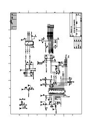
Chapter 7. Schematic Diagram<br />
Notes:<br />
1. All resistance values are indicated in " "<br />
(k=10 , M=10 ).<br />
2. All capacitance values are indicated in "uF"<br />
(p=10 uF).<br />
3 6<br />
-6<br />
Version: 1.0<br />
Page 15/18
S ervice SW-5.<br />
1 <strong>3000</strong><br />
Guide<br />
Chapter 7. Schematic Diagram<br />
Notes:<br />
1. All resistance values are indicated in " "<br />
(k=10 , M=10 ).<br />
2. All capacitance values are indicated in "uF"<br />
(p=10 uF).<br />
3 6<br />
-6<br />
Version: 1.0<br />
Page 16/18
S ervice SW-5.<br />
1 <strong>3000</strong><br />
Guide<br />
Chapter 8. Important Notes<br />
8.1 Packing requirement for sending the PCB assembly by post<br />
PCB assembly is a kind of sophisticated electronic circuit board. Well packing<br />
will be required when sending them by post.<br />
* Some sophisticated IC components are mounted on the PCB assembly, hence<br />
it is necessary to pack each PCB assembly with a separate static protecting bag,<br />
in order to avoid static electricity.<br />
* Reliable external packing is also very important when sending the PCB assembly<br />
by post, in that it would avoid unnecessarily lost or damage.<br />
8.2 Short of spare parts while repairing a speaker system<br />
If you are short of spare parts when you have some speaker systems waiting to<br />
be repaired, it would be recommended to take the necessary parts from one<br />
speaker system, so that you may have the as many speaker systems<br />
Version: 1.0<br />
Page 17/<br />
18