SW-5.1 1505 Service Guide .pdf - Genius
SW-5.1 1505 Service Guide .pdf - Genius
SW-5.1 1505 Service Guide .pdf - Genius

You also want an ePaper? Increase the reach of your titles
YUMPU automatically turns print PDFs into web optimized ePapers that Google loves.
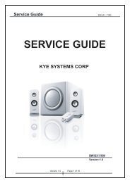
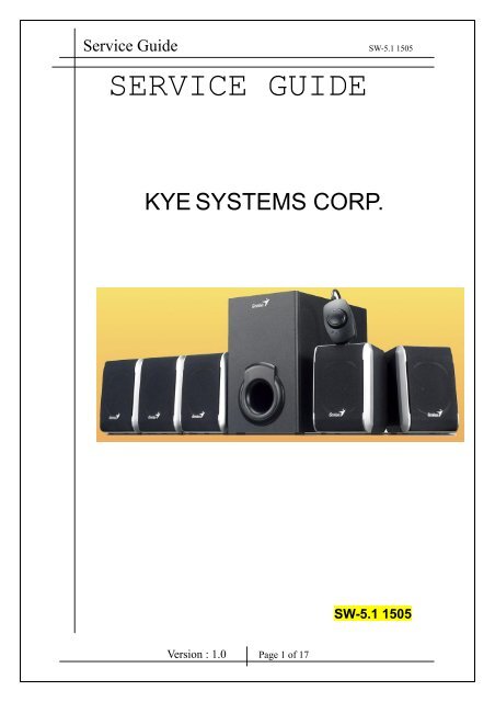
<strong>Service</strong> <strong>Guide</strong> <strong>SW</strong>-<strong>5.1</strong> <strong>1505</strong><br />
SERVICE GUIDE<br />
KYE SYSTEMS CORP.<br />
<strong>SW</strong>-<strong>5.1</strong> <strong>1505</strong><br />
Version : 1.0 Page 1 of 17
<strong>Service</strong> <strong>Guide</strong> <strong>SW</strong>-<strong>5.1</strong> <strong>1505</strong><br />
Revision History<br />
Version Date Change<br />
1.0 6/24/2009<br />
Version : 1.0 Page 2 of 17
<strong>Service</strong> <strong>Guide</strong> <strong>SW</strong>-<strong>5.1</strong> <strong>1505</strong><br />
Table of Contents<br />
Revision History …………………………………………………………………….2<br />
Table of Contents ……………………………………………………………………3<br />
Getting Started ………………………………………………………………………4<br />
Conventions Used in this <strong>Guide</strong> ……………………………………….4<br />
Safety Precautions ……………………………………………………..4<br />
Chapter 1. How to Handle Defective Returns……………………………………..5<br />
1.1 Overview …………………………………………………………..5<br />
1.2 Problems …………………………………………………………...6<br />
1.2.1 One or more channels no sound ………………..…7<br />
1.2.2 Wired Control no function..……………………..…7<br />
1.2.3 Power LED (indicator) no light………………....…8<br />
1.2.4 Volume , Bass no function...……..……….………..8<br />
Chapter 2. Specifications ………………………………………….………………9<br />
Chapter 3. Block Diagram …………………………………………….………….10<br />
Chapter 4. Exploded View ………………………………………….………….11~13<br />
Chapter 5. Part List ………………………………………….…………………14~15<br />
Chapter 6. Schematic Diagram ………….……………………...………….……..16<br />
Chapter 7. Important Notes ……………………………………………….………17<br />
7.1 Packing Requirement for Sending the PCB Assembly by Post. …..17<br />
7.2 Short of Spare Parts while Repairing a Speaker System ………..…17<br />
Version : 1.0 Page 3 of 17
<strong>Service</strong> <strong>Guide</strong> <strong>SW</strong>-<strong>5.1</strong> <strong>1505</strong><br />
Getting Started<br />
Conventions Used in this <strong>Guide</strong><br />
Pay Special Attention : Instructions that are important to remember and<br />
may prevent mistakes .<br />
Caution : Information that, if not followed, may result in damage to the<br />
product .<br />
Safety Precautions<br />
The following precautions should be observed in handling the speaker<br />
Described in this guide :<br />
Place the speakers on a flat, level and stable surface.<br />
Do not place the speakers in environments subject to mist, smoke,<br />
vibration, excessive dust, salty or greasy air, or other corrosive gases<br />
and fumes.<br />
Do not drop or jolt the speakers.<br />
Do not allow anything to drop into the subwoofer case through its<br />
ventilator, as it could result in fatal electric shock or fire .<br />
Place the unit far enough from other equipments for good heat<br />
dissipation .<br />
Disconnect the AC power cord from the AC outlet before performing<br />
any maintenance on the speakers .<br />
Do not perform any maintenance with wet hand .<br />
Prevent foreign substances, such as water, other liquids or chemicals ,<br />
From entering the speakers while performing maintenance procedures<br />
on the speakers .<br />
Version : 1.0 Page 4 of 17
<strong>Service</strong> <strong>Guide</strong> <strong>SW</strong>-<strong>5.1</strong> <strong>1505</strong><br />
Chapter 1. How to Handle Defective Returns<br />
1.1 Overview<br />
Receiving Defective speakers from<br />
Customers<br />
Verifying problems<br />
Proceeding necessary tests<br />
Function NG<br />
Analyzing possible malfunction<br />
causes<br />
Function NG<br />
Deciding & proceeding the<br />
rectification methods<br />
Function OK<br />
Replace necessary defective parts<br />
Proceeding tests to<br />
Verify if the speaker is<br />
functioning normally<br />
Function OK<br />
Return the speakers with proper<br />
repackaging to customers<br />
Version : 1.0 Page 5 of 17
<strong>Service</strong> <strong>Guide</strong> <strong>SW</strong>-<strong>5.1</strong> <strong>1505</strong><br />
1.2 Problems<br />
Item<br />
Problem Description<br />
1.2.1 One or more channels no sound<br />
1.2.2 Wired Control no function<br />
1.2.3 Power LED (indicator) no light<br />
1.2.4 Volume , Bass no function<br />
Version : 1.0 Page 6 of 17
<strong>Service</strong> <strong>Guide</strong> <strong>SW</strong>-<strong>5.1</strong> <strong>1505</strong><br />
Attention<br />
Please follow the numbered sequence marked within parenthesis given in individual<br />
Flow chat, in that this is the best-recommended sequence to rectify the problems.<br />
1.2.1 One or more channels no sound<br />
1.2.1 One or more channels no sound<br />
Problem<br />
One or more channels no sound<br />
Analyzer and<br />
Identify the Causes<br />
Broken or short circuit<br />
Defective<br />
U1, U2, U3, U4,U5,<br />
U6,U7, VR1 , VR2<br />
wired control cable<br />
PCBA connect cable<br />
Speaker cable dis-connect<br />
or speaker damaged<br />
Solutions<br />
Check solder points on<br />
PCB<br />
Check and Replace<br />
defective IC<br />
Re-connect speaker<br />
cable or replace<br />
defective speaker(s)<br />
1.2.2 Wired Control no function<br />
Problem<br />
Wired control no function<br />
Analyzer and<br />
Identify the Causes<br />
Broken or short circuit<br />
on PCBA<br />
Defective<br />
U1, U2, U3, U4,U5,<br />
U6,U7, VR1<br />
3 pin cable dis-connect<br />
or damaged<br />
Solutions<br />
Check solder points on<br />
PCBA<br />
Check and Replace<br />
defective IC, VR1<br />
Re-connect cable or<br />
replace defective cable<br />
Version : 1.0 Page 7 of 17
<strong>Service</strong> <strong>Guide</strong> <strong>SW</strong>-<strong>5.1</strong> <strong>1505</strong><br />
1.2.3 Power LED (indicator) no light<br />
Problem<br />
Power LED (indicator) no light<br />
Analyzer and<br />
Identify the Causes<br />
Power switch or LED<br />
defective<br />
Defective D2~D5<br />
POWER , R2 , LED<br />
wired control cable<br />
AC cord of transformer<br />
disconnected or defective<br />
Re-solder or replace<br />
Solutions<br />
defective component(s)<br />
1.2.4 Volume , Bass no function<br />
Problem<br />
Volume , Bass no function<br />
Analyzer and<br />
Identify the Causes<br />
Broken or short circuit<br />
Volume: Defective VR1<br />
Bass: Defective VR2<br />
Solutions<br />
Check solder points on PCB<br />
Check and Replace defective<br />
components<br />
Version : 1.0 Page 8 of 17
<strong>Service</strong> <strong>Guide</strong> <strong>SW</strong>-<strong>5.1</strong> <strong>1505</strong><br />
Chapter 2. Specifications<br />
Woofer<br />
NO. Description Unit Specifications<br />
1 Out Power at THD 10% W ≧ 17<br />
2 Sensitivity mV 130 ± 30<br />
3 Freq. Response (Top -3dB) Hz 30 ~ 150 ± 10%<br />
4 S/N ratio dB ≧ 70<br />
5 Hum & Noise (Vol.: max) mV ≦ 2<br />
Center<br />
NO. Description Unit Specifications<br />
1 Out Power at THD 10% W ≧ 6<br />
2 Sensitivity mV 550 ± 50<br />
3 Freq. Response (Top -3dB) Hz 100 ~ 20K ± 10%<br />
4 S/N ratio dB ≧ 70<br />
5 Hum & Noise (Vol.: max) mV ≦ 2<br />
Satellite<br />
NO. Description Unit Specifications<br />
1 Out Power at THD 10% W ≧ 6<br />
2 Sensitivity mV<br />
3 Freq. Response (Top -3dB) Hz<br />
FL,FR=650 ± 60<br />
SL,SR=500 ± 60<br />
FL,FR=70 ~ 20K ± 10%<br />
SL,SR=80 ~ 20K ± 10%<br />
4 Separation dB ≧ 40<br />
5 S/N ratio dB ≧ 70<br />
6 Hum & Noise (Vol.: max) mV ≦ 2<br />
Version : 1.0 Page 9 of 17
<strong>Service</strong> <strong>Guide</strong> <strong>SW</strong>-<strong>5.1</strong> <strong>1505</strong><br />
Chapter 3. Block Diagram<br />
AUDIO IN<br />
FR,FL. Satellite<br />
Volume<br />
Control<br />
Wired Control Box<br />
Power<br />
Amplifier<br />
SR,SL. Satellite<br />
Center<br />
Woofer<br />
Woofer Volume<br />
FILTER<br />
AC IN<br />
Transformer &<br />
Rectifier<br />
Version : 1.0 Page 10 of 17
<strong>Service</strong> <strong>Guide</strong> <strong>SW</strong>-<strong>5.1</strong> <strong>1505</strong><br />
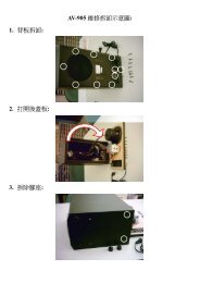
Chapter 4. Exploded View<br />
Woofer<br />
Version : 1.0 Page 11 of 17
<strong>Service</strong> <strong>Guide</strong> <strong>SW</strong>-<strong>5.1</strong> <strong>1505</strong><br />
Satellite<br />
Version : 1.0 Page 12 of 17
<strong>Service</strong> <strong>Guide</strong> <strong>SW</strong>-<strong>5.1</strong> <strong>1505</strong><br />
Wired Control Box<br />
Version : 1.0 Page 13 of 17
<strong>Service</strong> <strong>Guide</strong> <strong>SW</strong>-<strong>5.1</strong> <strong>1505</strong><br />
Chapter 5. Part List<br />
No. DESCRIPTION Qty UNIT Part No.<br />
1 <strong>SW</strong>-<strong>5.1</strong> <strong>1505</strong>/Body/Satellite-FL 1 PC 29-101-01<br />
2 <strong>SW</strong>-<strong>5.1</strong> <strong>1505</strong>/Body/Satellite-FR 1 PC 29-101-02<br />
3 <strong>SW</strong>-<strong>5.1</strong> <strong>1505</strong>/Body/Satellite-SL 1 PC 29-101-03<br />
4 <strong>SW</strong>-<strong>5.1</strong> <strong>1505</strong>/Body/Satellite-SR 1 PC 29-101-04<br />
5 <strong>SW</strong>-<strong>5.1</strong> <strong>1505</strong>/Body/Satellite-Center 1 PC 29-101-05<br />
6 Loud speaker-front, 3” 4 ohm 6W 2 PC 29-100-01<br />
7 Loud speaker-surround, 3” 4 ohm 6W 2 PC 29-100-02<br />
8 Loud speaker, 3” 4 ohm 6W 1 PC 29-100-03<br />
9 Rubber pad(satellite), <strong>SW</strong>-<strong>5.1</strong> 3005 20 PC 26-100-01<br />
10 <strong>SW</strong>-<strong>5.1</strong> <strong>1505</strong>/Body/Woofer-120V-US<br />
29-101-06<br />
11 <strong>SW</strong>-<strong>5.1</strong> <strong>1505</strong>/Body/Woofer-230V-EU 29-101-07<br />
1 PC<br />
12 <strong>SW</strong>-<strong>5.1</strong> <strong>1505</strong>/Body/Woofer-240V-AU 29-101-08<br />
13 <strong>SW</strong>-<strong>5.1</strong> <strong>1505</strong>/Body/Woofer-240V-UK 29-101-09<br />
14 Loud speaker, 4” 4 ohm 20W 1 PC 29-100-04<br />
15 Rubber pad(woofer), <strong>SW</strong>-<strong>5.1</strong> <strong>1505</strong> 4 PC 29-100-05<br />
16 IC, STA540SA 2 PC E1065-48<br />
17 IC, UTC4558 3 PC 25-100-05<br />
18 IC, PT2325-D 1 PC E1065-49<br />
19 IC, L7809CV 1 PC E1065-50<br />
20 VR1, <strong>SW</strong>-<strong>5.1</strong> <strong>1505</strong> 1 PC E1075-21<br />
21 Transformer, 120V:12VAC & 2.5A<br />
E1074-145<br />
22 Transformer, 230V:12VAC & 2.5A 1 PC E1074-146<br />
23 Transformer, 240V:12VAC & 2.5A E1074-147<br />
24 PCBA, <strong>SW</strong>-<strong>5.1</strong> <strong>1505</strong> 1 PC 29-101-10<br />
25<br />
Audio cable, 3.5mm (green) to<br />
RCA jack (red/white)<br />
1 PC E1066-31<br />
Version : 1.0 Page 14 of 17
<strong>Service</strong> <strong>Guide</strong> <strong>SW</strong>-<strong>5.1</strong> <strong>1505</strong><br />
26<br />
27<br />
Audio cable, 3.5mm (orange) to<br />
RCA jack (red/white)<br />
Audio cable, 3.5mm (blue) to<br />
RCA jack (red/white)<br />
1 PC E1066-32<br />
1 PC E1066-33<br />
28 3 pin cable, <strong>SW</strong>-<strong>5.1</strong> 3005 1 PC E1066-47<br />
29 Wired Control 1 Set 29-101-11<br />
30 S/N Label ( on woofer & Gift Box ) 2 PC 29-102-01<br />
31 Manual, <strong>SW</strong>-<strong>5.1</strong> <strong>1505</strong> 1 PC 12030396100-A<br />
32 Cushion, <strong>SW</strong>-<strong>5.1</strong> <strong>1505</strong> 1 Set 29-102-02<br />
33 Gift Box, <strong>SW</strong>-<strong>5.1</strong> <strong>1505</strong> 1 PC 12000467100-A<br />
34 Carton, <strong>SW</strong>-<strong>5.1</strong> <strong>1505</strong> 0.5 PC 12100364100-A<br />
Version : 1.0 Page 15 of 17
<strong>Service</strong> <strong>Guide</strong> <strong>SW</strong>-<strong>5.1</strong> <strong>1505</strong><br />
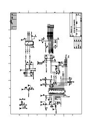
Chapter 6. Schematic Diagram<br />
Version : 1.0 Page 16 of 17
<strong>Service</strong> <strong>Guide</strong> <strong>SW</strong>-<strong>5.1</strong> <strong>1505</strong><br />
Chapter 7. Important Notes<br />
7.1 Packing Requirement for Sending the PCB Assembly by Post<br />
PCB assembly is a kind of sophisticated electronic circuit board. Well<br />
packing will be required when sending them by post.<br />
* Some sophisticated IC components are mounted on the PCB assembly,<br />
hence it is necessary to pack each PCB assembly with a separate static<br />
protecting bag, in order to avoid static electricity.<br />
* Reliable external packing is also very important when sending PCB<br />
assembly by post, in that it would avoid unnecessarily lost or damage.<br />
7.2 Short of Spare Parts while Repairing a Speaker System<br />
If you are short of spare parts when you have some speaker systems waiting<br />
to be repaired, it would be recommended to take the necessary parts form<br />
one speaker system, so that you may have the as many speaker systems.<br />
Version : 1.0 Page 17 of 17