
Tags
It is very easy to take the view that the quartz revolution represented some sort of cataclysm for traditional watchmaking. I have cast a contemptuous eye myself over mid 1970’s watch catalogues filled to bursting with seemingly uninspiring vanilla quartz output, smarting at the relegation of proper watches to the obscurity of the back pages. However, the view we tend to take of quartz technology is shaped by our modern-day perspective of the quartz movement as a disposable plastic consumable, produced by robots for pennies and that watches powered by them are therefore somehow contemptible.
That viewpoint neglects, of course, the reality of the engineering achievement of those pioneering quartz technology watchmakers of the late 1960’s and early ‘70’s. There was a very good reason why early quartz watches were priced at a very considerable premium over the established mechanical wristwatch, and it wasn’t simply opportunistic marketing of white heat technological trinketry to consumers thirsty for ways to spend their disposable income.

Extract from the 1975 domestic market catalogue comparing 085x King Quartz models (top) with automatic mechanical King Seiko models (bottom). The quartz-powered models were priced at about twice that of the mechanical equivalents.
The reason they were so expensive was because the movements that powered them were magnificent, ingenious, complex, beautifully over-engineered feats magic. And in many cases, housed in very high-quality cases and furnished with artisanal dials and handsets. These were exotic beasts.
We’ve met previously one of the earliest examples of vintage Seiko quartz exotica in a 3823 VFA from 1973, and a later incarnation in the 4822 from 1975. The older 38 series first appeared in 1971 and marked the beginning of the mass-produced stepper motor-controlled quartz watch. Most of the early Seiko quartz movements up to about 1974 were the product of the Suwa division in Nagano but towards the end of 1972, the Daini Seikosha division stepped up to the plate with the properly exotic, slightly quirky 3922/3923 produced from late 1972. The 3922/23 was a thirteen jewel V.F.A. movement employing an electromagnetic escapement rather than the stepper motor of the 38 series but inevitably, when Daini joined the mass-produced quartz game two years later, it was with a stepper motor design. The 08 series was introduced towards the end of 1974 and was used in QT, QZ and King Quartz branded watches. The QT series used the 0822/23; the QZ, the 0841/42/43 and the highest-end King Quartz, the 0852/53. Rather than simply contributing a redundant range of Daini quartz models for the sake of it, these watches were pitched at a price point 20 to 30% lower than the 38 series equivalents. As we shall see, that differential probably correctly reflects a genuine difference in quality in the movements.
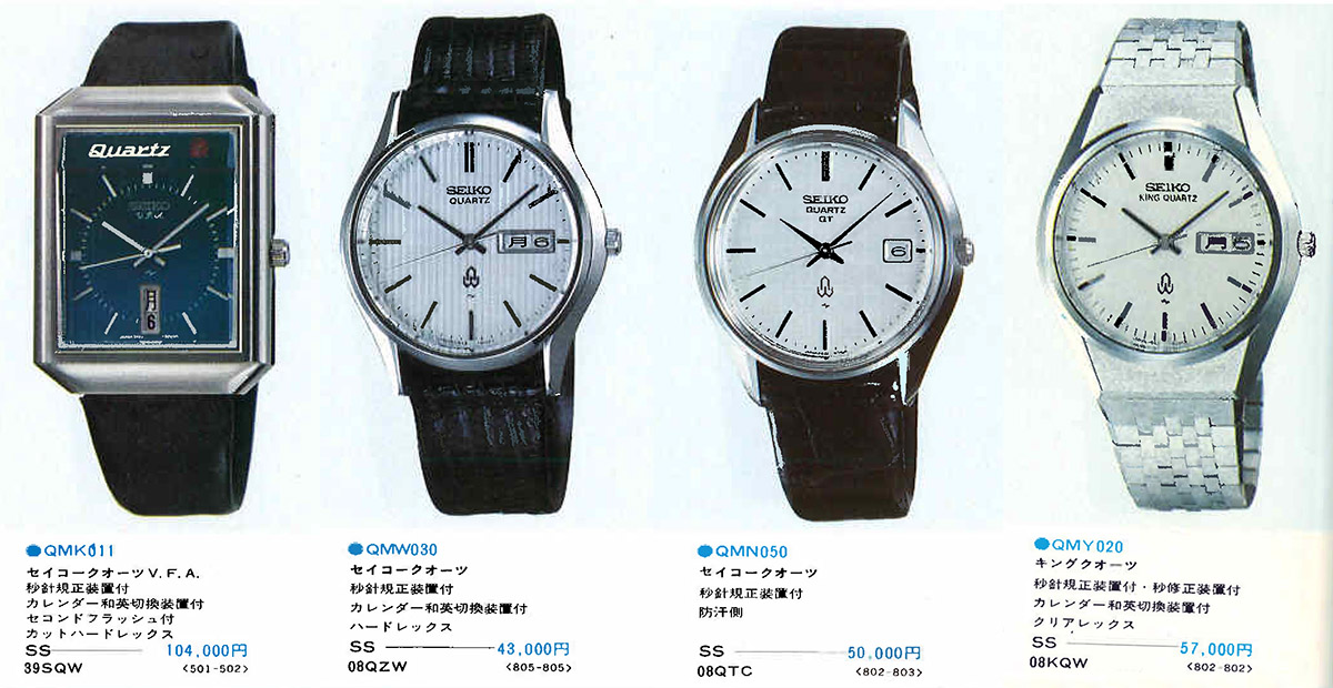
The first Daini Seikosha quartz watch was the exotic 13 jewel electromagnetic escapement 3922/23 (far left). The three levels of Daini 08 series stepper-motor quartz watches: QZ, QT and King Quartz (left to right). Note the price increments.
In each case, the calibres ending in a 2 featured a date only calendar while those ending in a 3, day/date. 1 signified no calendar. Although the three variants shared the same base architecture, they differed in some aspects of their design and in the features offered: all three are temperature-compensated 9 jewel quartz movements running at 32,768 Hz, but the 0822/3 is rated at 15s/month compared to the 10s/month of the 0842/3 and 0852/3. The latter two both feature trimmer condensers, all the better for regulation. All three feature stop seconds, quickset calendars, bilingual day calendars. The 0852/3 features one brilliant feature that we’ll get to later on, not featured in either of the lesser versions.
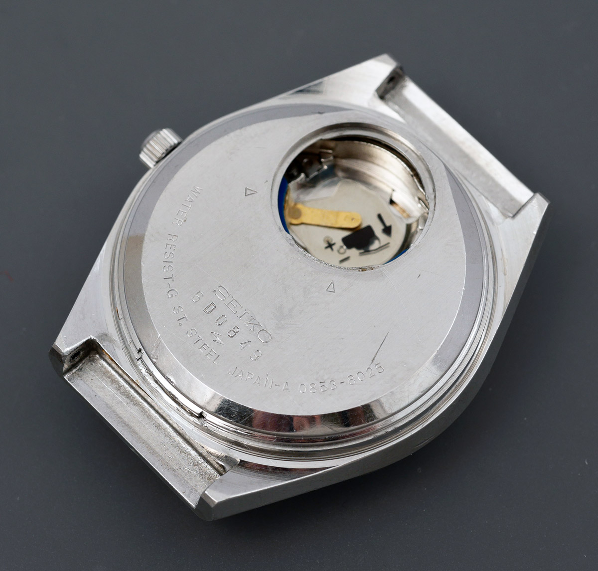
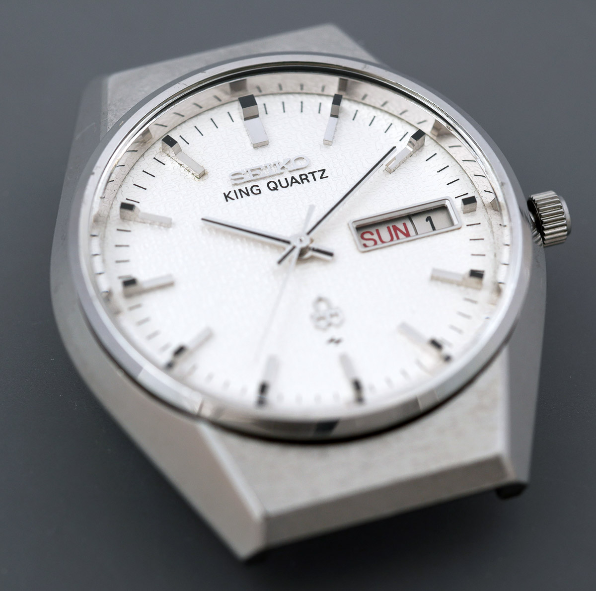
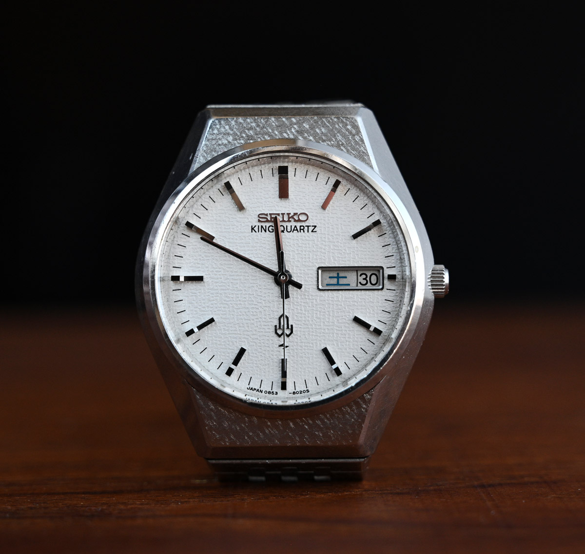
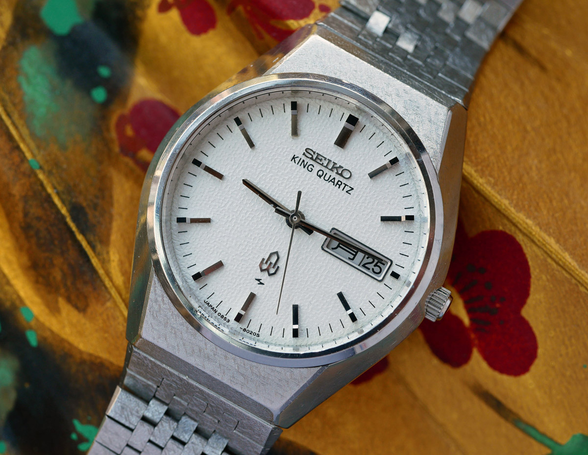
It’s time to introduce the subject of today’s entry: a Seiko King Quartz 0853-8025 from December 1976. The Yahoo auction photo does nothing much to entice but enticed I was, nonetheless.
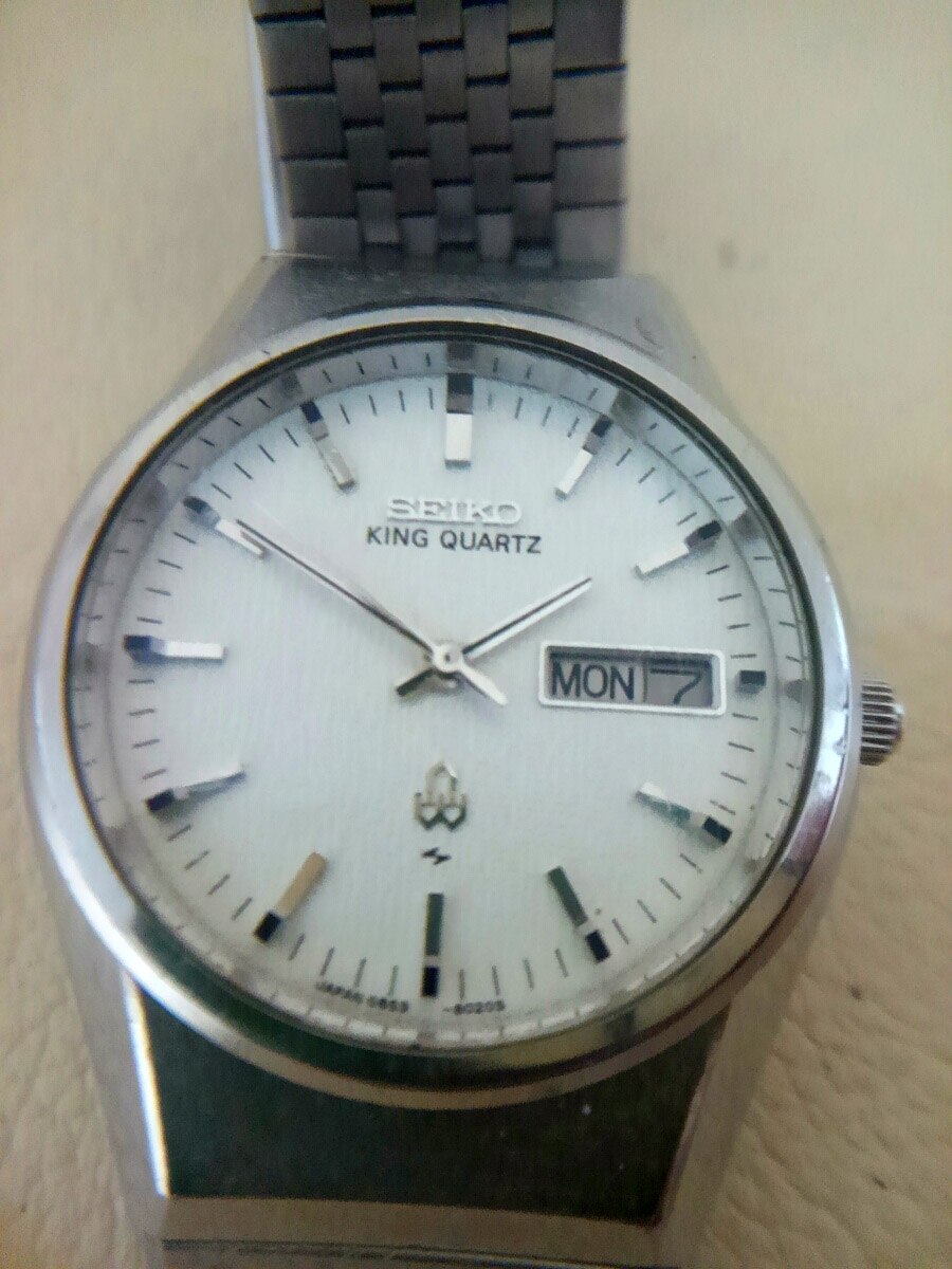 This photo shows little of the dial texture, even less of the case but it does appear to suggest that the dial and handset are very clean and that the case is in good condition. Somehow, I failed to photograph the complete watch on arrival before beginning to break it down and so this will have to do by way of an introduction. I should observe however that this appears to be the model shown far right in the catalogue compilation shown next photo up the page. In fact, this model enjoys a whole feature page to itself in the 1976 Seiko domestic market watch catalogue.
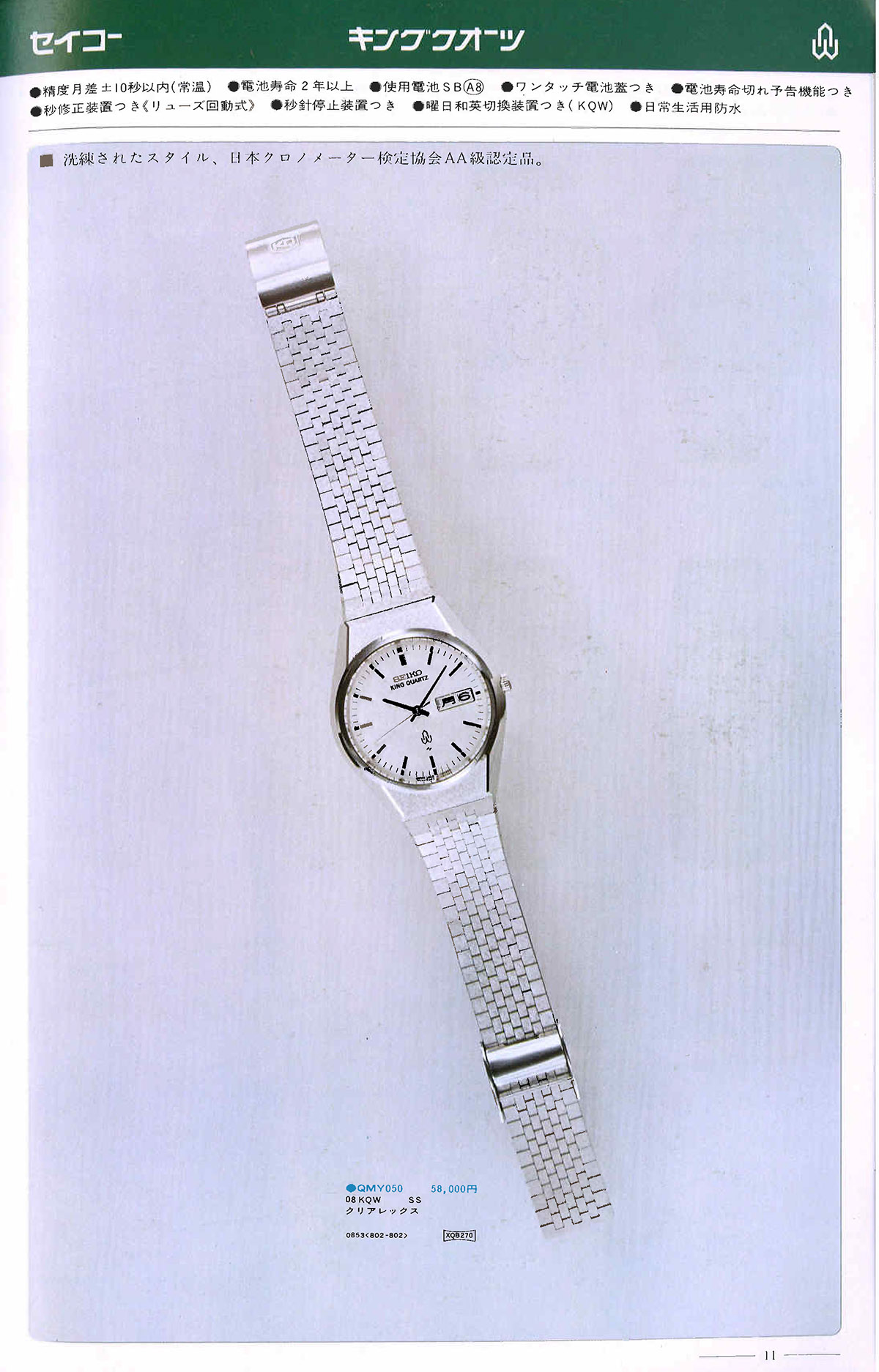 The bulleted features at the top of the page in the image above translate as: •Monthly accuracy 10 seconds (room temp) • two year battery life • one touch battery lid • battery life expiration warning • quick crown second correction device • second hand stop device • day to day English/Japanese language switching device • waterproof for everyday life
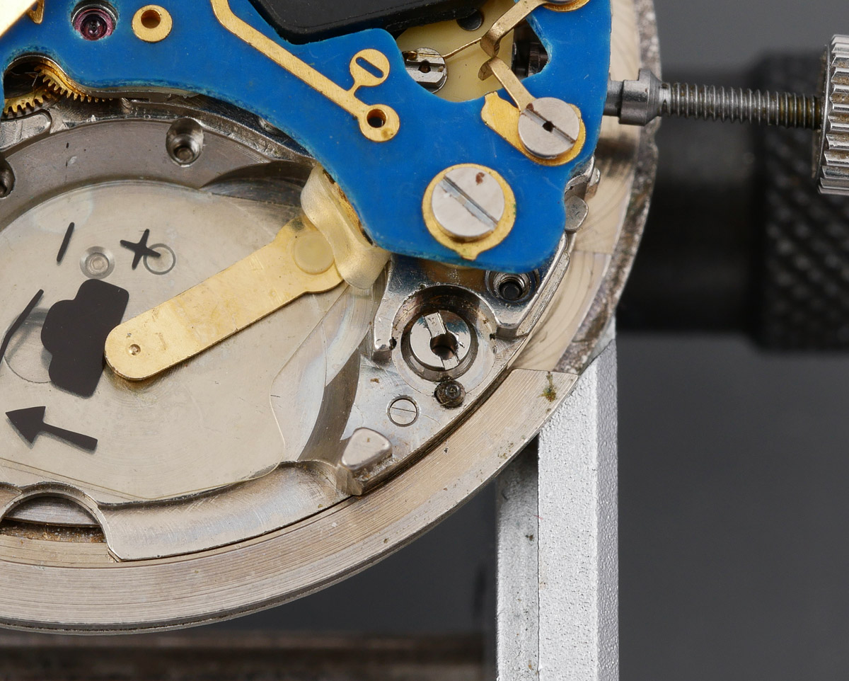
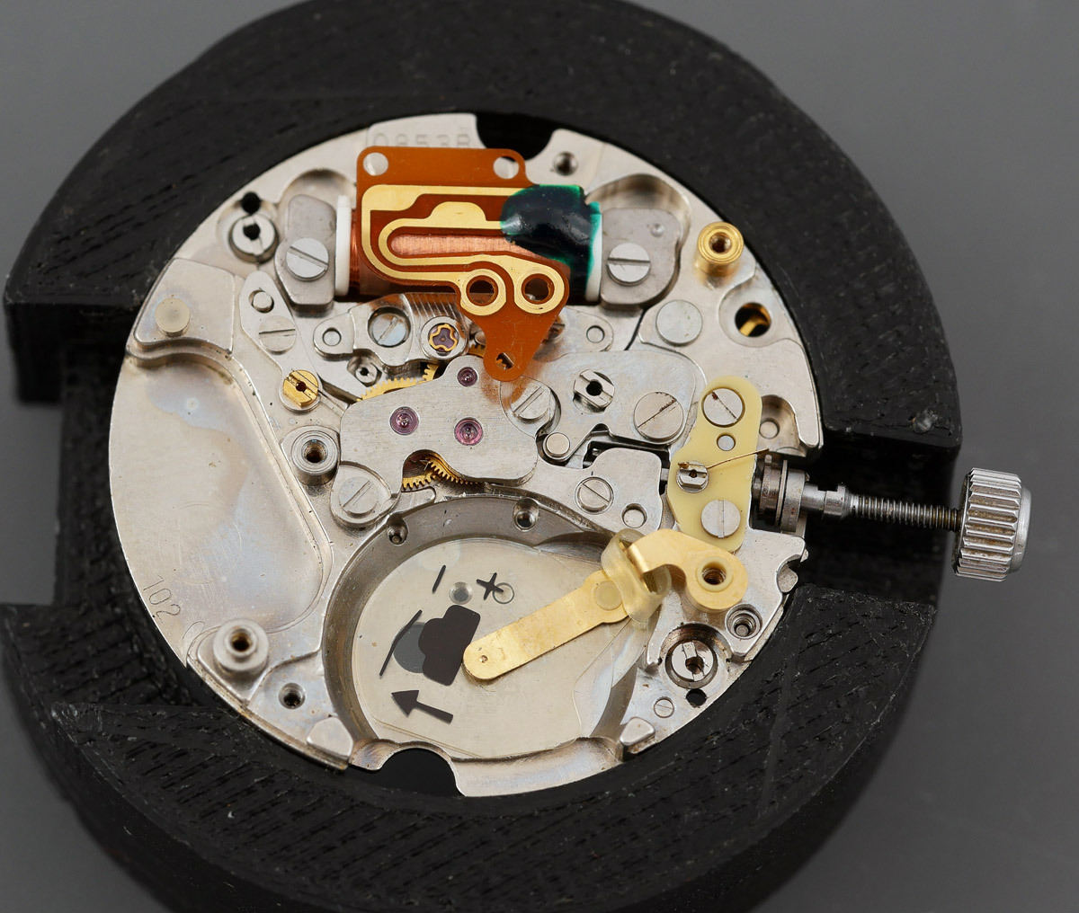
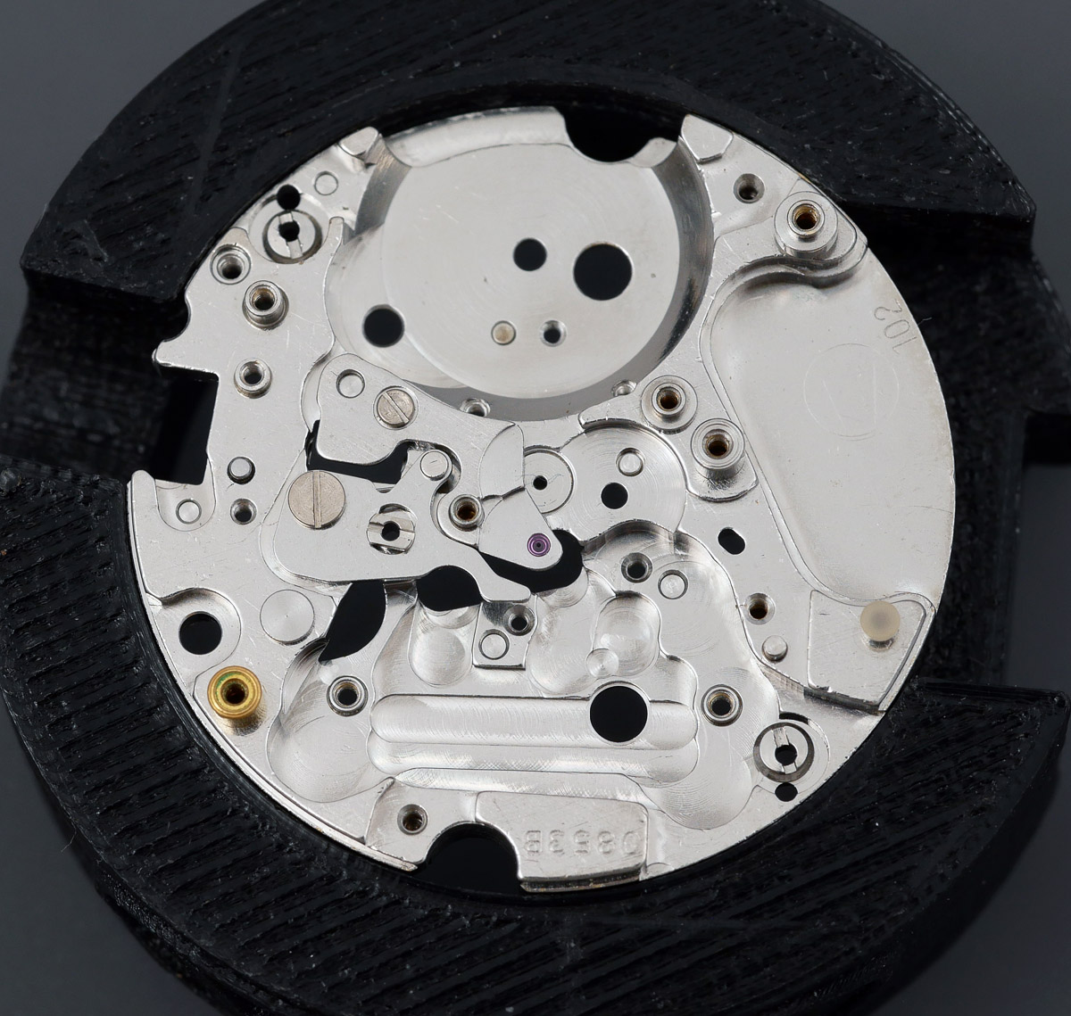
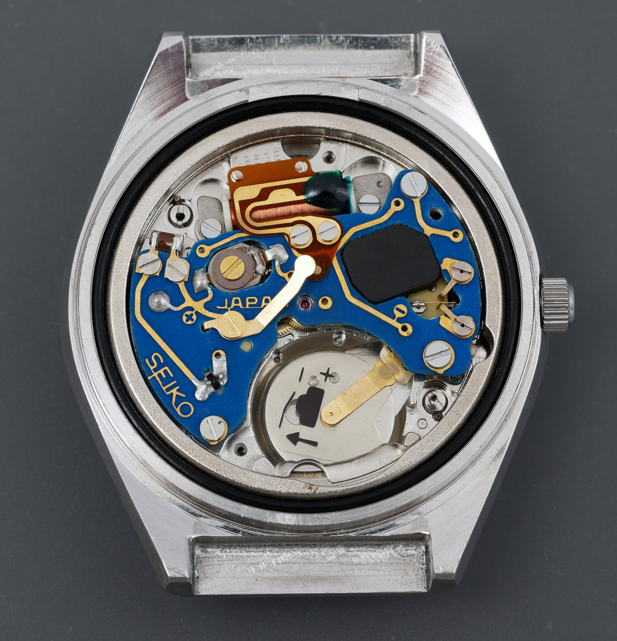
There must be more to this watch than the typically anemic Seiko catalogue photos suggest. Let’s see if we can’t unearth what that might be. We join proceedings at the point at which I have removed the snap on case back, revealing the movement, the battery and case back gasket already removed.
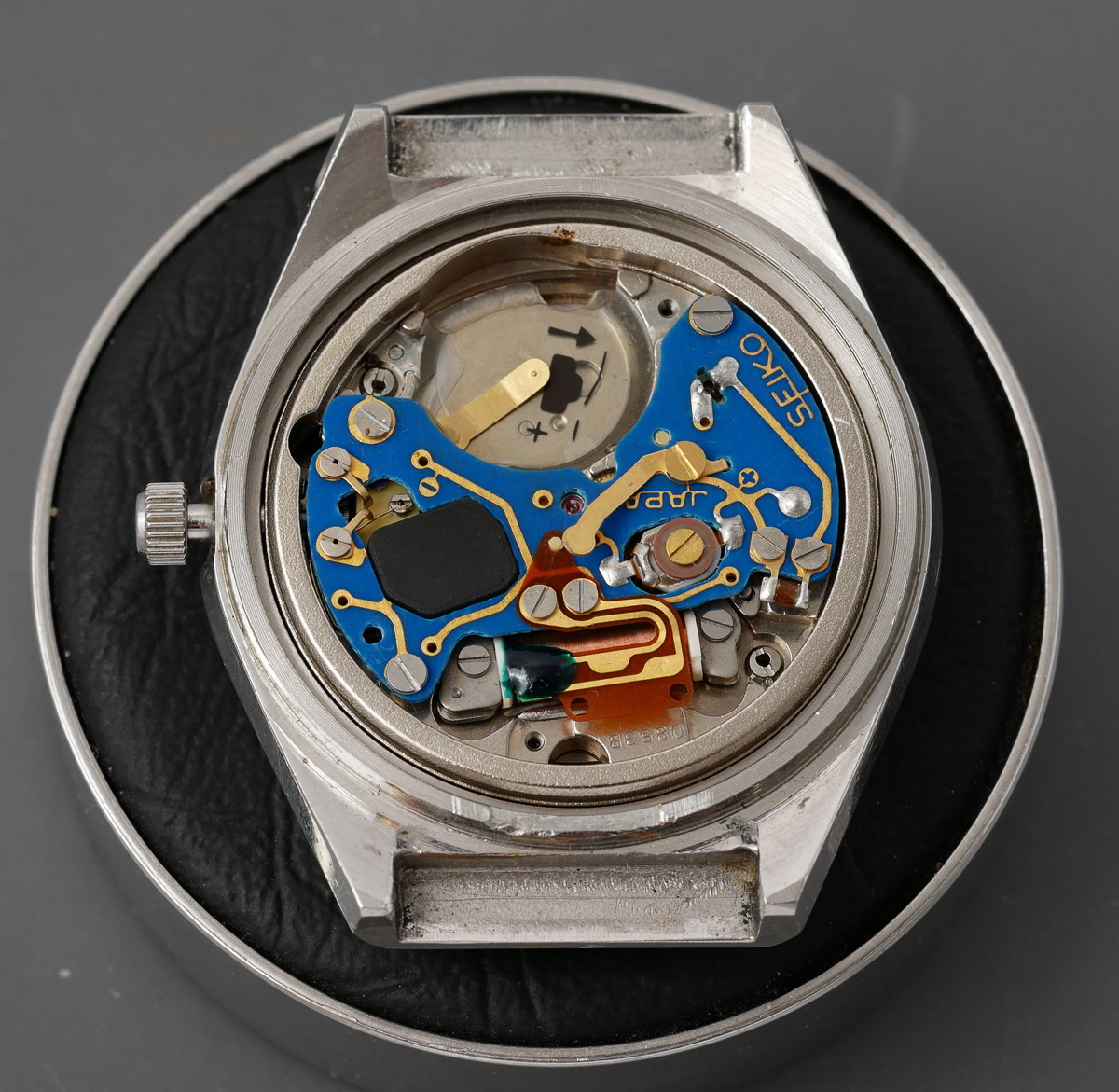 The eagle-eyed among you may note that this is the 0853B variant of the movement, which is consistent with this being a December 1976 watch. The movement is surrounded by a substantial case ring which we must remove to gain access to the stem release lever prior to removing the movement from the case.
 This photo does not quite reveal how beautiful this dial is, but you should be able to make out that it features a paper texture to its surface, wonderfully executed and topped off with a set of clean and mostly crisp hands. The dial feet are secured to the movement using a pair of eccentric pins that we turn 180 degrees to release their grip.
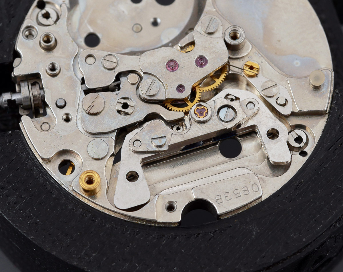
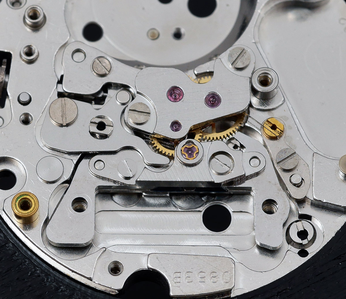
 With the dial and hands removed, the calendar-side initially presents as conventionally arranged but we soon discover multi-layered engineering complexity typical of the Daini approach to their movement design at the time. They just wanted to show off!
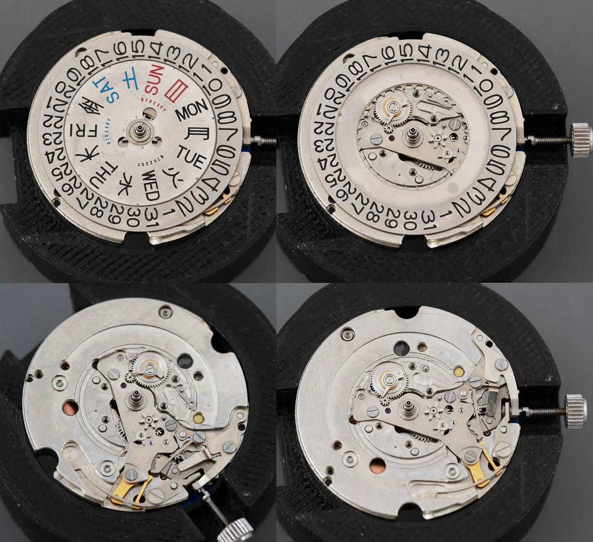 This is not the rat’s nest of intimidation of the 5106 but it is, nonetheless at another level compared with, say, the calendar function of a 6146. Some of this complexity serves the secret functionality of this movement that I’ve hinted at (and revealed if you’ve been reading carefully) but we’ll get back to that. At this point, we turn the movement over to tackle the train side.
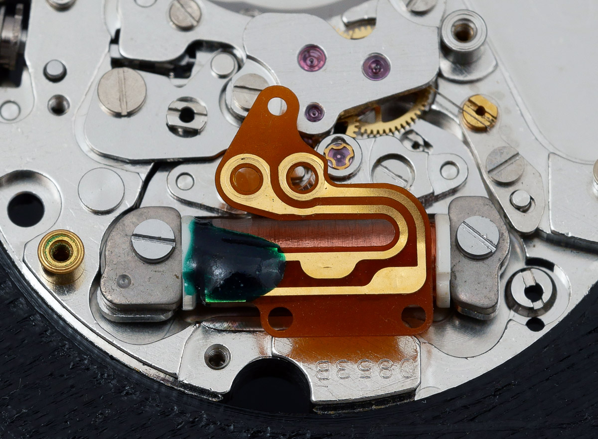
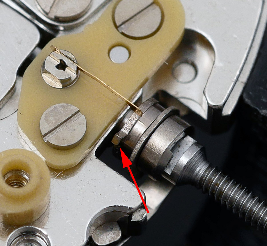
It is fair to say that this is not a particularly inspiring view, with the good stuff hidden almost entirely by the blue circuit board. This is not a movement to show off beneath a display case back. However, there are some details to enjoy such as the gold-tracked SEIKO and JAPAN.
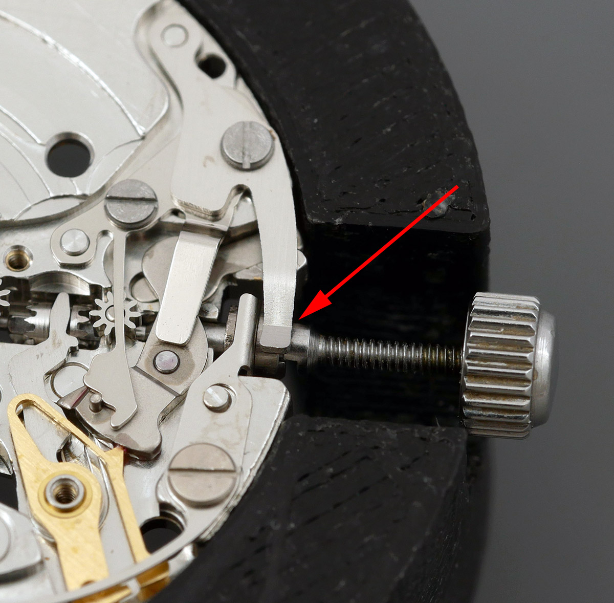
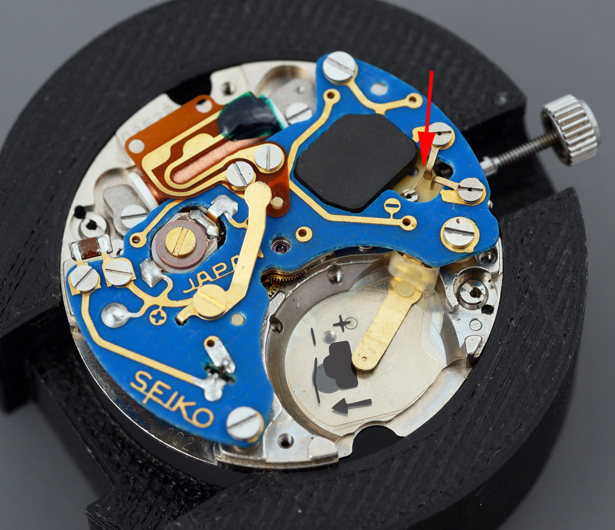 I’ve also indicated in the photo a curiosity: what is the purpose of those two arms adjacent to the red arrow and why is the tine emerging from region of the negative sign bent to the left of the upper most arm? My initial instinctive expectation, knowing nothing at this point of the purpose of these components, was that the tine should be sitting between the two arms, not off to one side. More of that later. The first step in proceeding is to remove the two lead terminal screws.
 Three screws hold the circuit board to the main plate and with those removed, the circuit comes away to reveal the train bridges beneath.
 This view provides an insight into the extent of the jeweling in this movement. We can see a curious miniature Diashock setting just underneath the terminal lead and presumably there’s another beneath. If this follows the same construction as a regular Diashock, then those two settings will account for four of the 9 jewels (and we can see already another three atop the gear train bridge).
We turn our attention next to the tine mounted on the yellow plastic insulating block adjacent to the stem. I can’t believe that the tine is supposed to be bent away from central like that and so suspect that this was the result of a clumsy refitting of the circuit block by a previous watchmaker, ignorant of the purpose of this component.
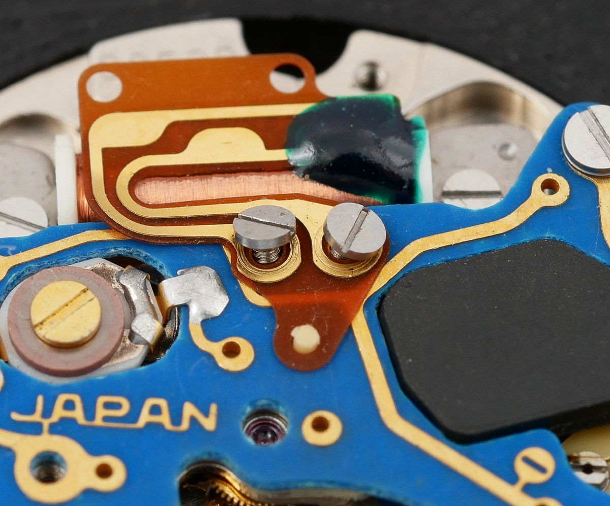
 I would encourage you to note the cam surrounding the stem and the small protuberance on the inner lobe. We can get a better view of the outer lobe in the photo below, taken following removal of the yellow insulating block and battery connector.
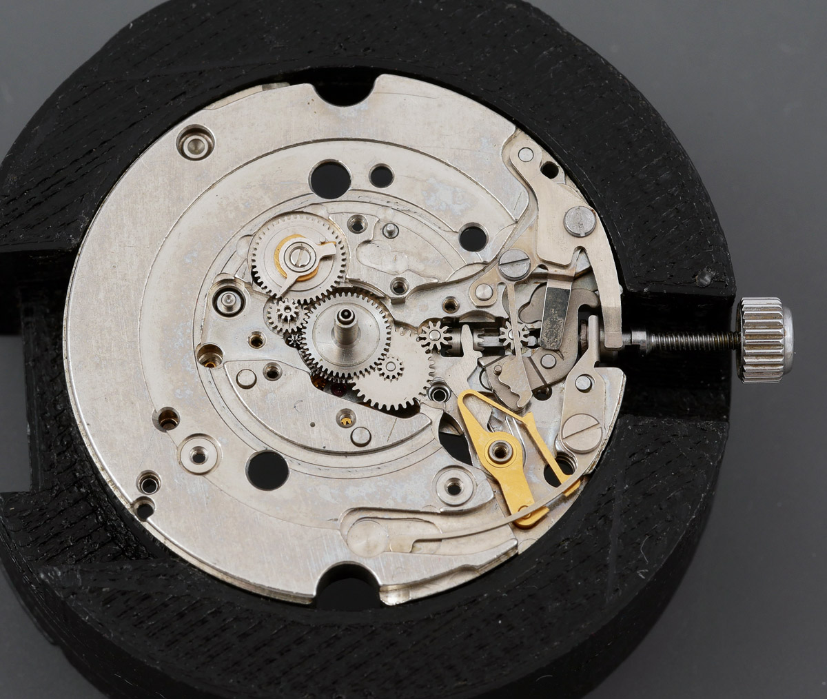
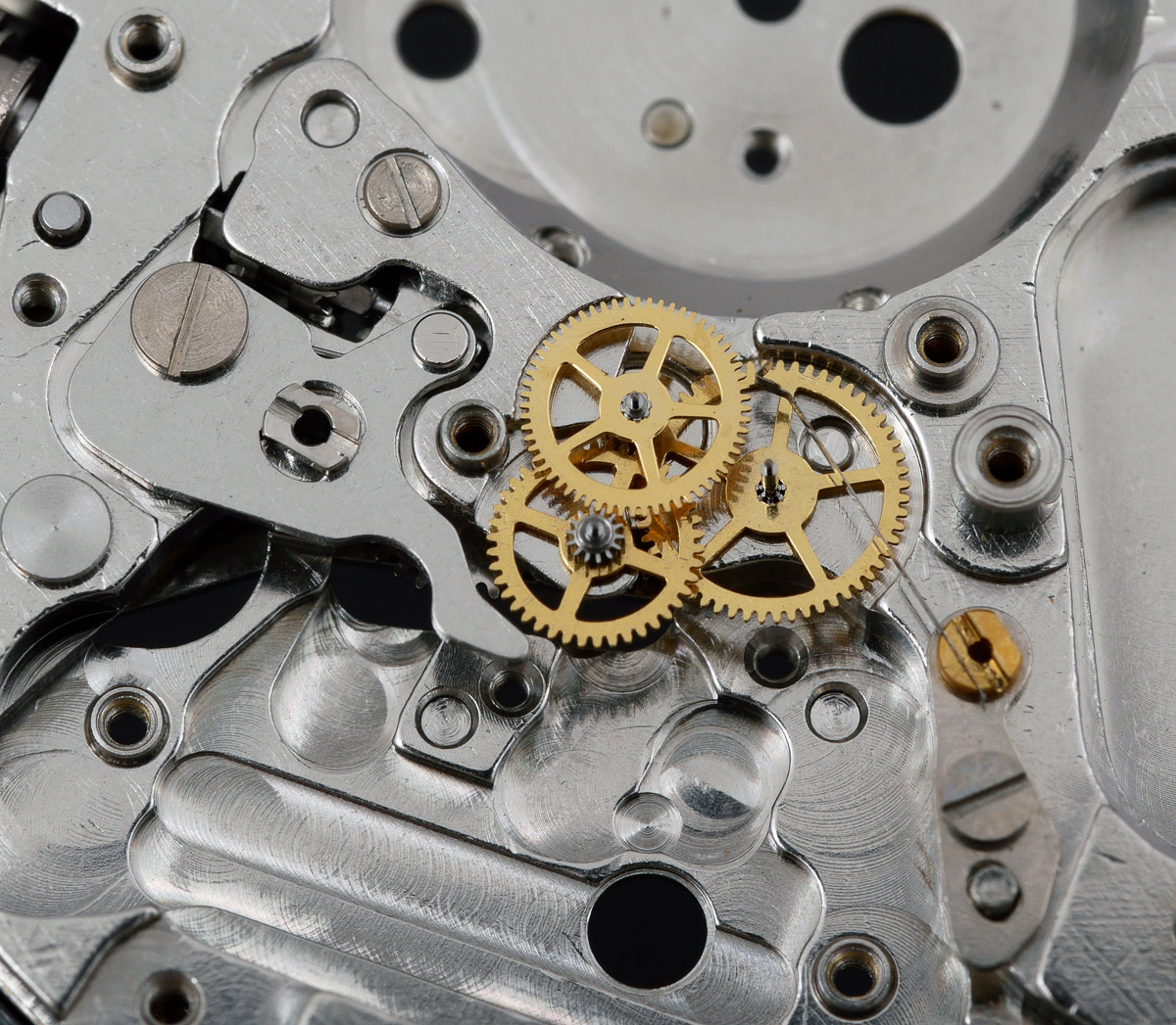
 Next we remove the coil (carefully) at which point we get a much better view of the essential layout of the gear train and bridges.
 The rather crude initial impressions given by the circuit board topping are revealed to have been a smokescreen. We can consider ourselves slightly intimidated at this point, knowing that we’ll be having to grapple with tiny Diashock springs in the near future where normally in a quartz movement any jeweling is limited to conventional single well ruby bearings. The Diashock settings support the step rotor, mounted in a motor block.
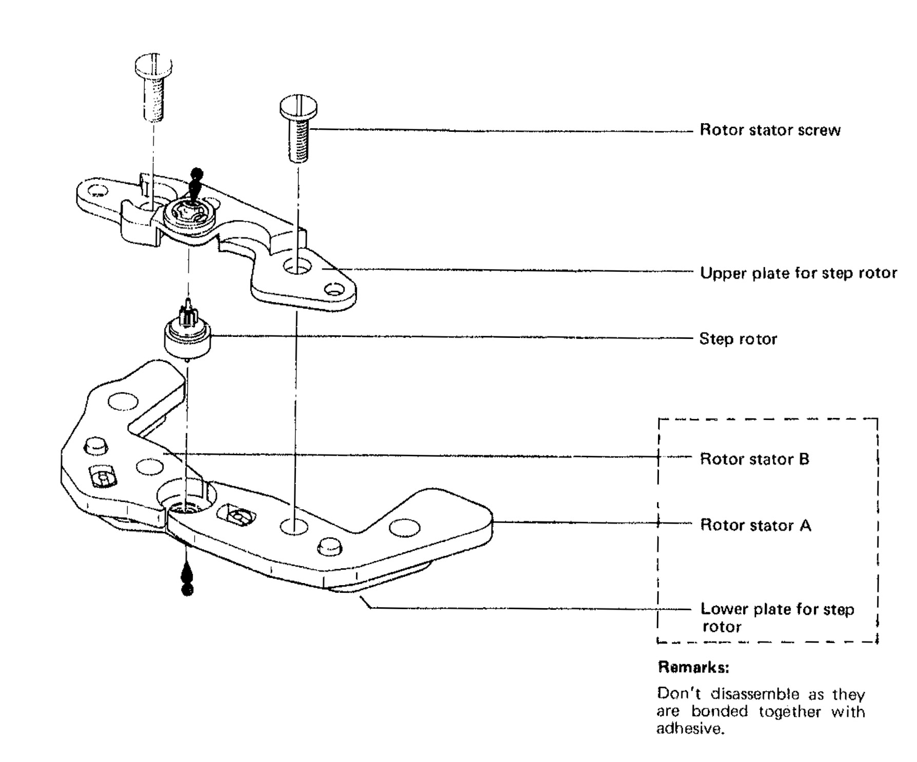
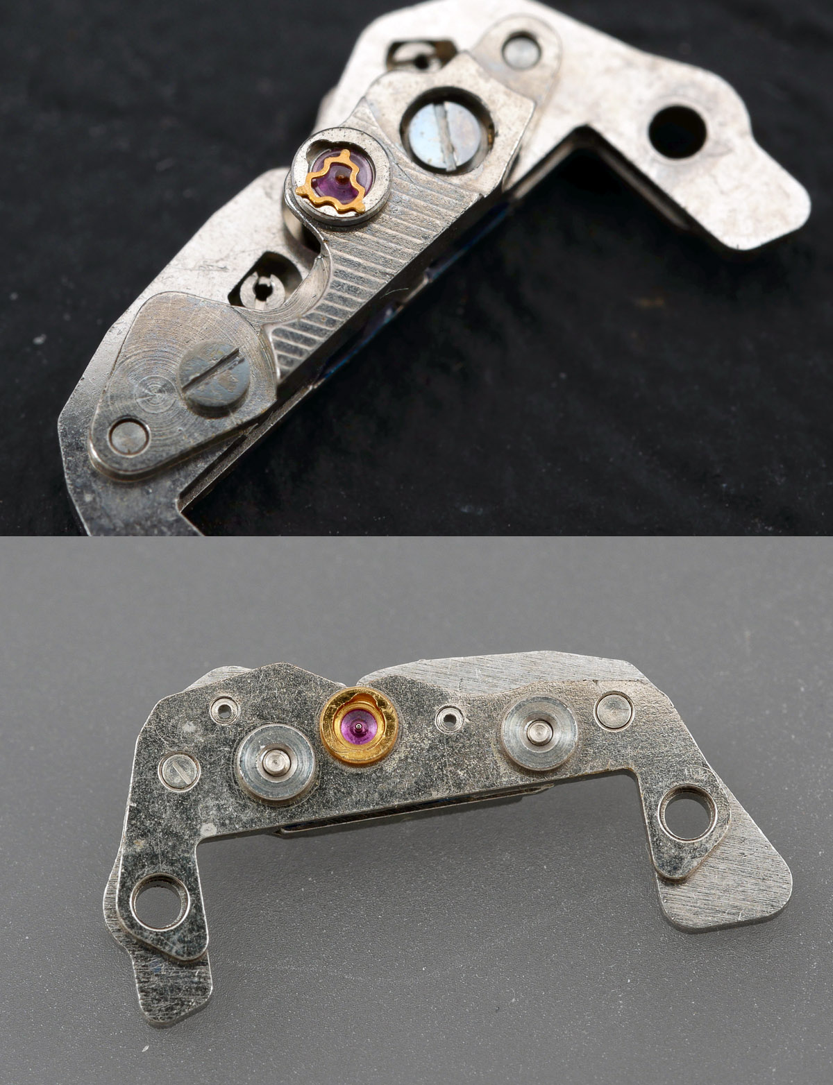 The motor block comprises the rotor stator, step rotor and upper plate, with the upper and lower pivots of the step rotor supported and protected by the two Diashock settings.
 The three train wheels (third, fourth and fifth wheels) are all supported by a single bridge and all benefit from jeweled bearings. The one additional complication that I anticipate when it comes to reassembling is the second jumper which is mounted on its own adjustable stage.
 Time to turn over and continue dismantling the setting mechanism.
 The essential layout here is reasonably conventional but complicated by the additional components whose role is to enable the operation of that mysterious profiled cam mounted on the stem. The cam is permanently mounted at the end of a lever spring and has to be removed together with the stem.
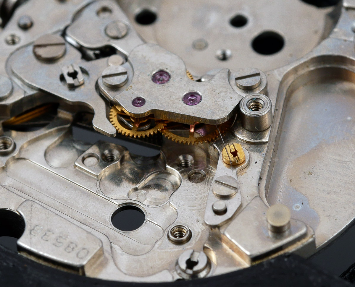
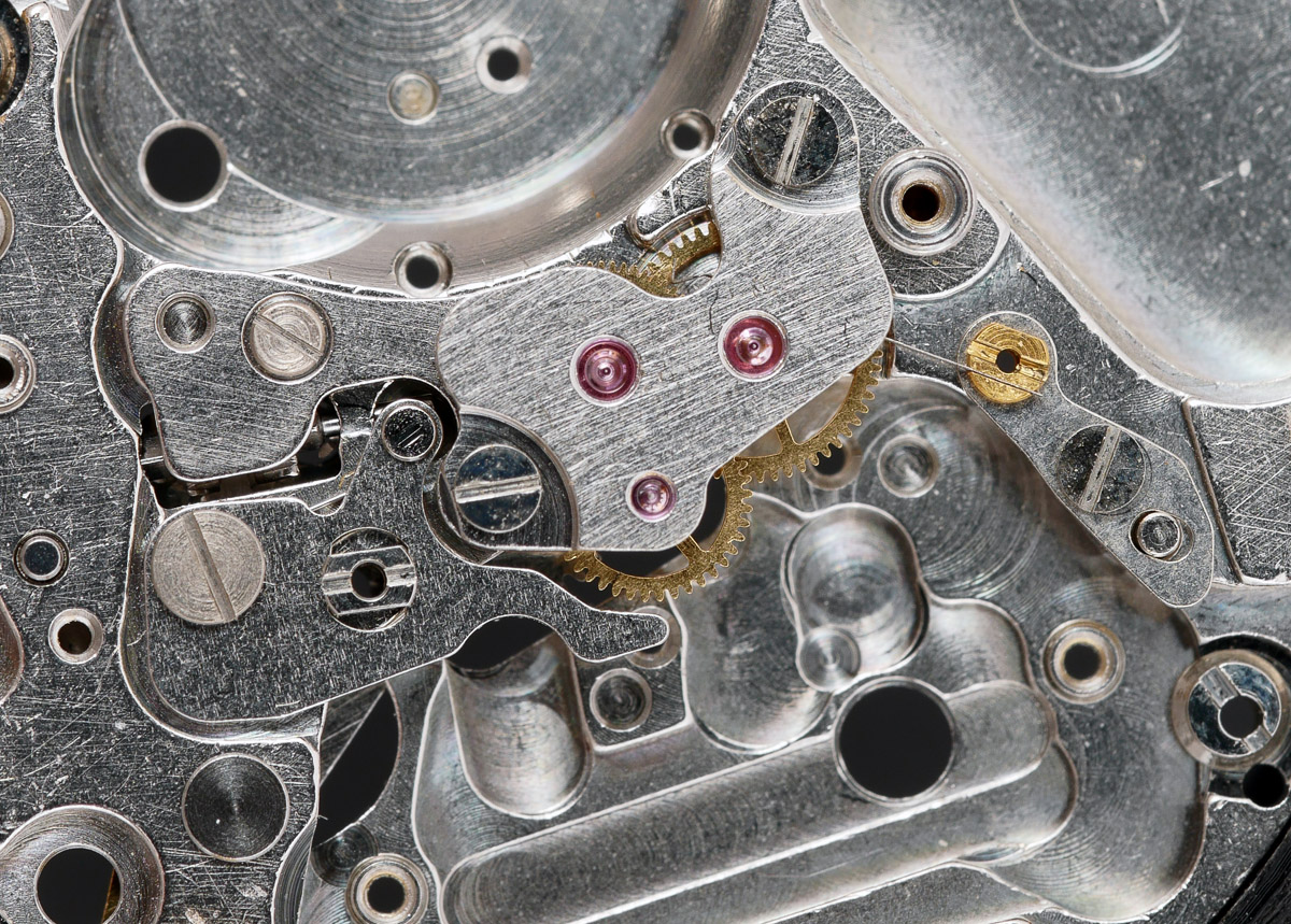
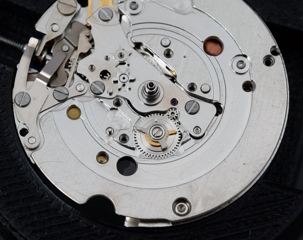
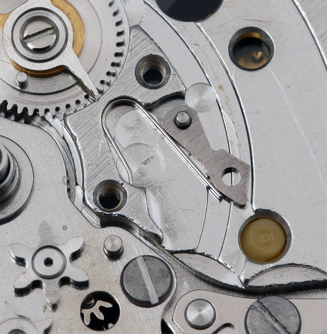
 The removal of the remaining parts on this side proceeded straightforwardly and so we turn our attention back to the gear train. Removing the gear train bridge reveals the three train wheels and the relationship that the seconds jumper has with the teeth on the fourth wheel.
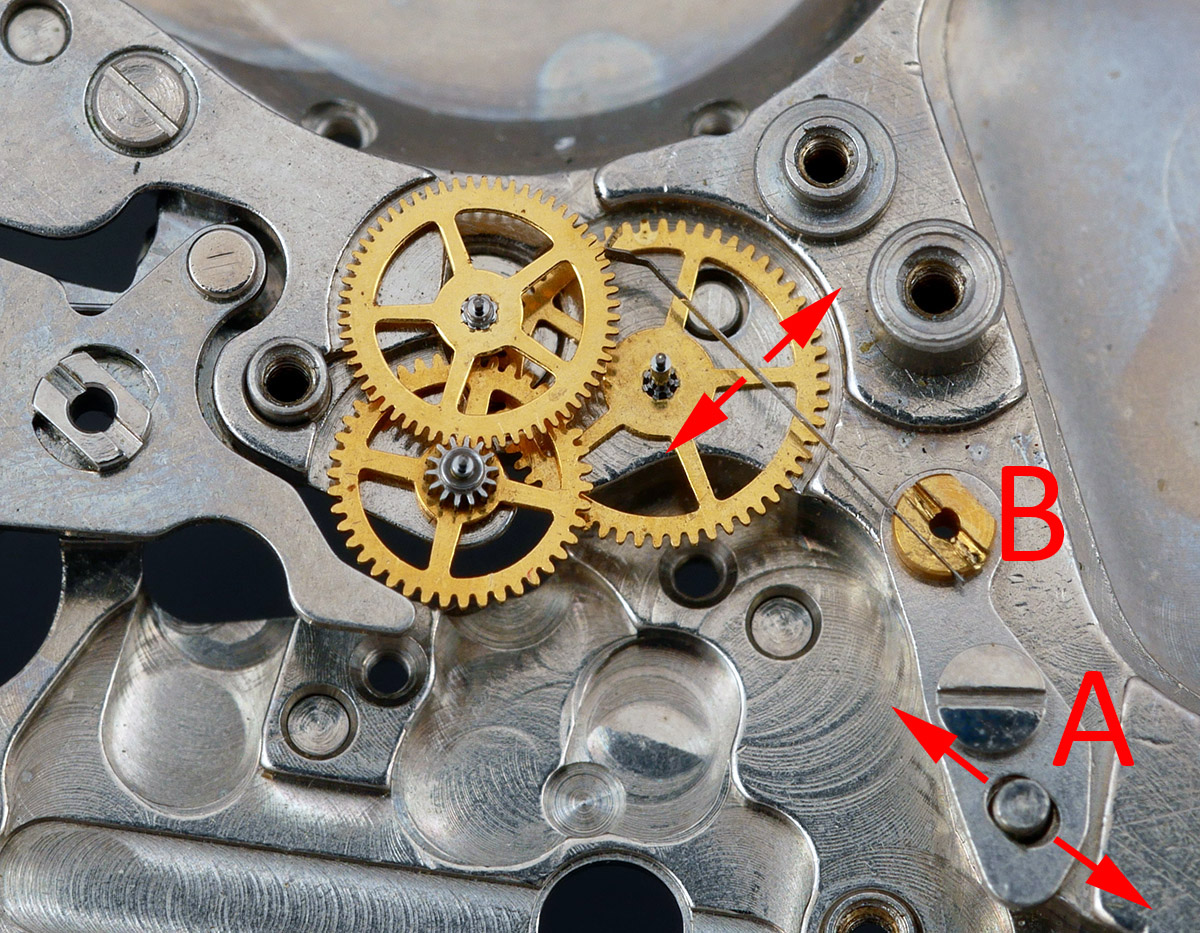 The seconds jumper is adjustable longitudinally by loosening screw A and then adjusting the position within the range permitted by the pin located in the oval hole and laterally by adjusting screw B. We’ll be working through that cycle later on. Next we need to remove the second setting lever and the lower bridge for the fifth wheel.
 Releasing the second setting lever requires the holding pin first to be rotated by 90 degrees before undoing the screw. This exposes the spring that we have to take care not to lose! Finally, the fifth wheel bridge can be removed.
At this point the main plate is naked and so all of the appropriate parts can go into the watch cleaning machine baskets ready for the cleaning machine. And off they go.
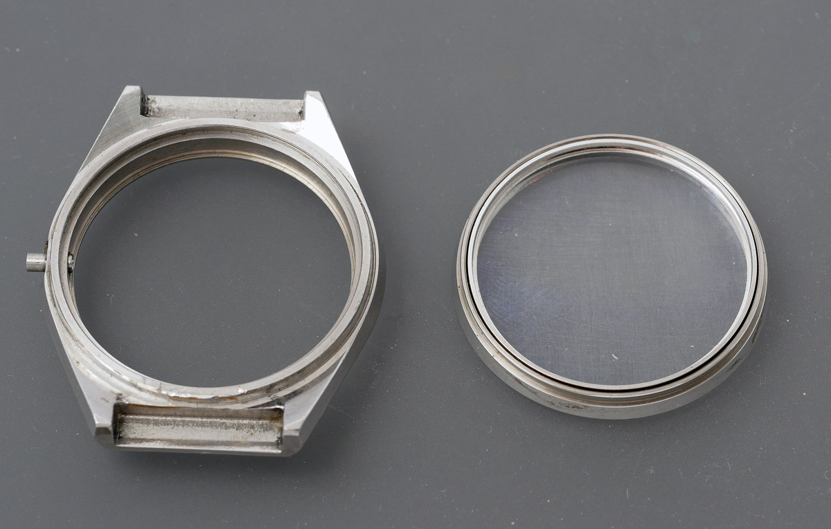
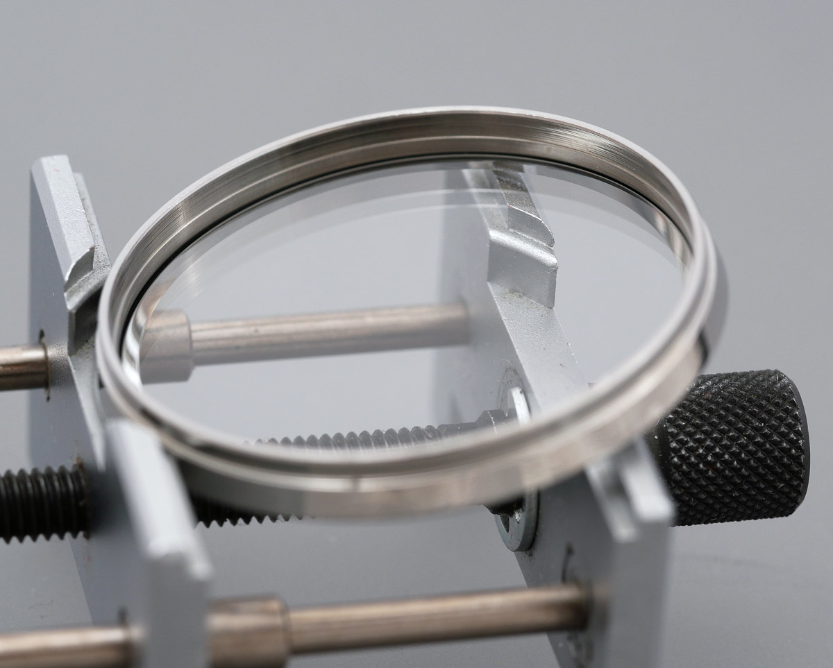
 The case design of this watch takes some figuring out. A conventional expectation in a watch with a removable case back and a bezel, is that the bezel should be removable from the crystal side, with the crystal itself then pushed out from inside or levered off from outside. However, with this case, there is no obvious way to remove the bezel, there being no visible notch in which to insert a case knife.
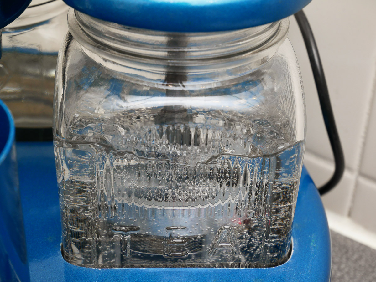
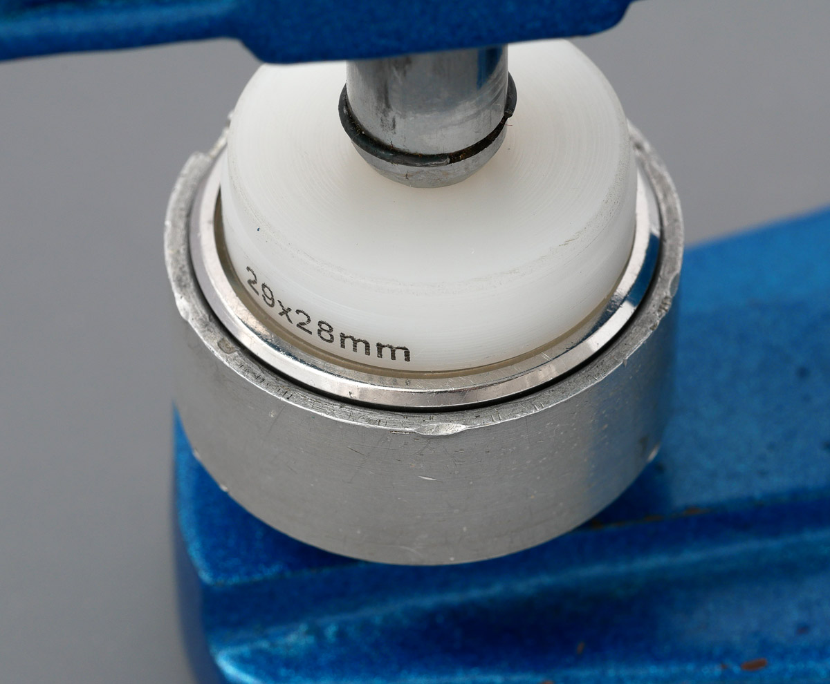
 I wondered whether a previous watchmaker might have refitted the bezel with the notch obscured by the case lugs but then took a closer look at how the crystal was seated. From inside the case, it appeared that the crystal was mounted into the rear of the bezel and held in place with a separate ring from the underside. A strategy to remove it began to take shape. I selected an appropriately sized press from my S-160 set, set the inverted case into an aluminium holder, large enough to accommodate the bezel, aligned the notch in the press with the inner part of the crown tube, and then pressed downwards, the press pushing against the metal ring and not the crystal itself.
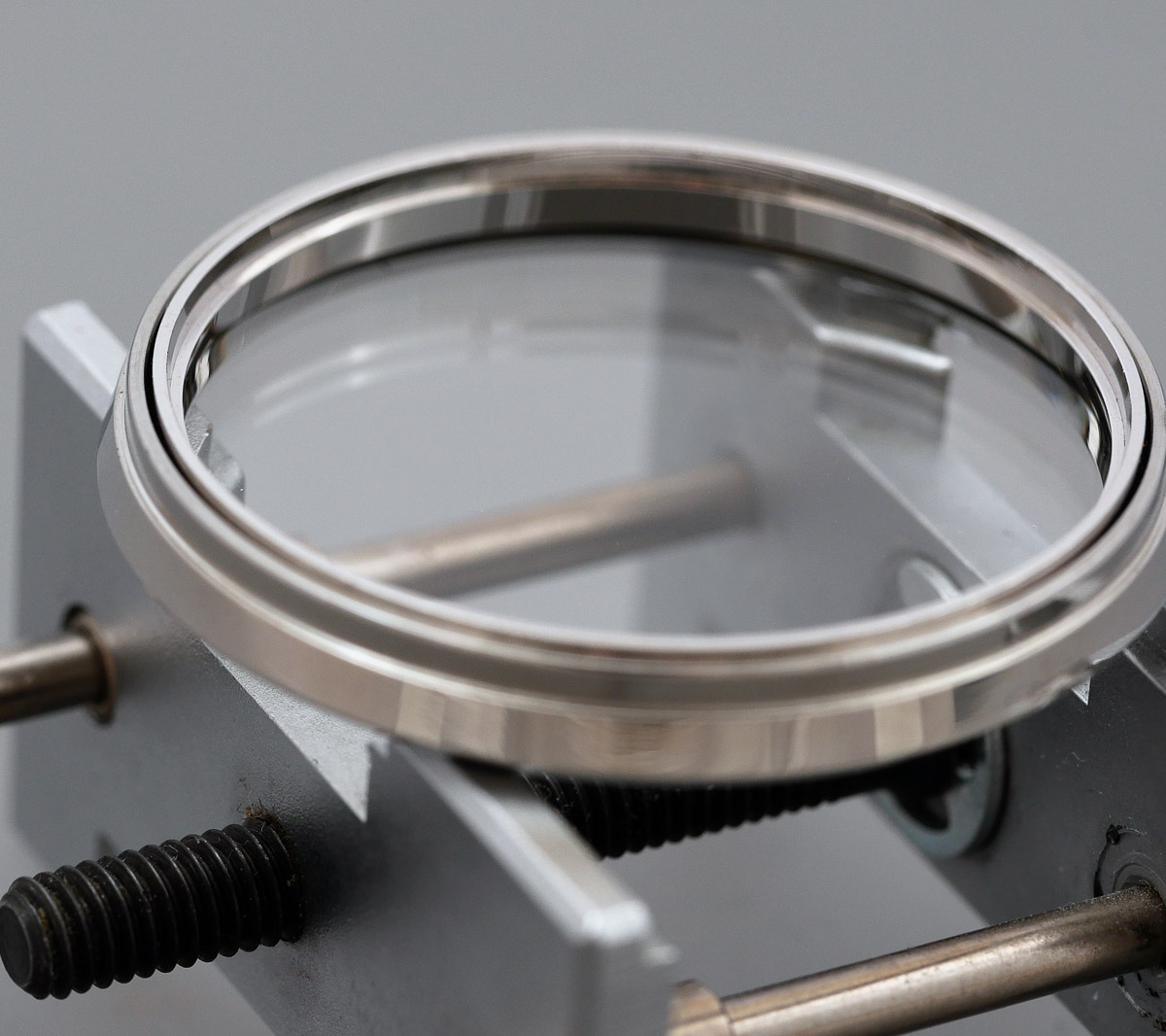
 This did the job, the whole unit emerging unscathed.
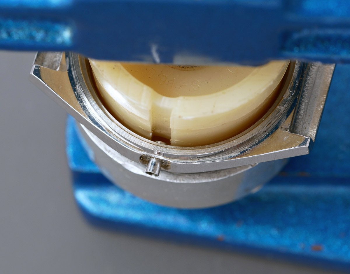
 The next step required the crystal to be pressed out from the bezel. Once again, with appropriately sized press and cup selected, the crystal presses out with a satisfying dull thwack.
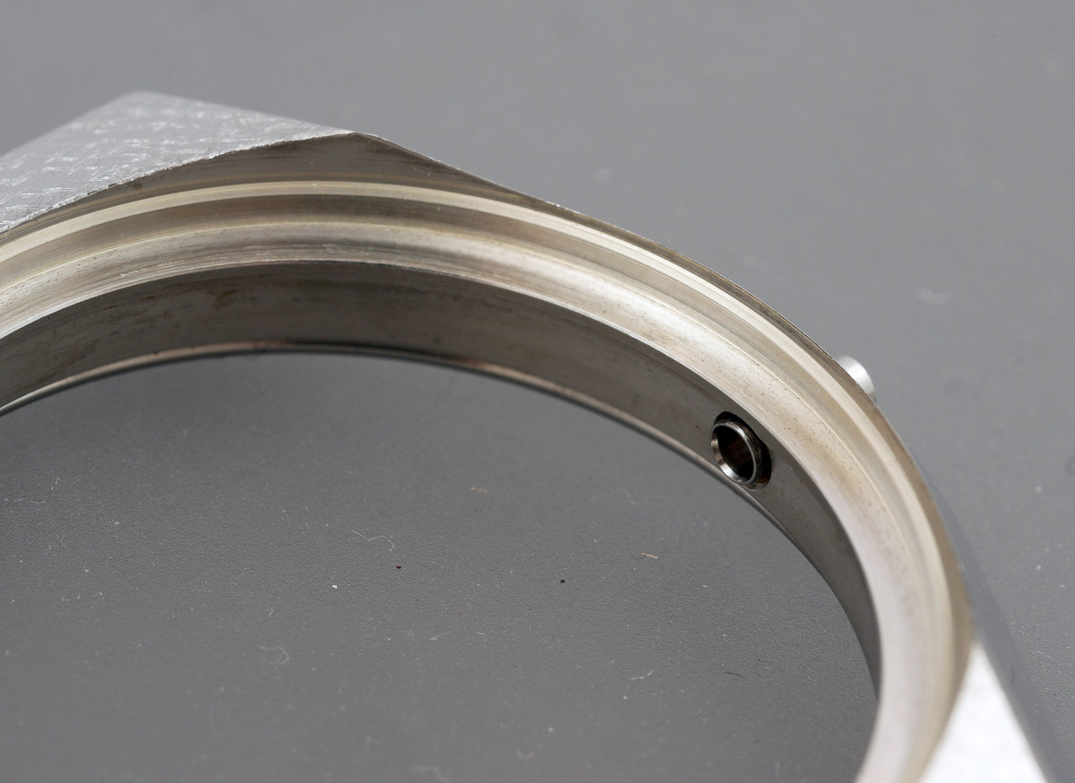
 The whole bezel assembly is sealed in the case using a nylon gasket.
 I then cleaned the whole case assembly ready for reassembly but that would have to wait until I’d figured out what crystal would substitute for the original and what rubber gasket to use to replace the one that seals the crystal in the bezel assembly. That process ended up taking a couple of weeks of trial and error, original spares being either unidentifiable or unavailable. We’ll re-join that battle later.
Reconstruction of the movement begins, as is my habit, by confronting the fiddliest job first. In this case, I reckon that must be the Diashock settings on the motor block.
 The step rotor is then fitted to the rotor stator before fitting the upper plate.
 We can now start to refit components to the main plate, starting with the fifth wheel bridge and the seconds setting lever.
 This proved to be somewhat more challenging and time consuming than I had hoped. The business of refitting the seconds setting lever spring was really quite fiddly and in a casual moment, I allowed the spring to make a bid for freedom. It achieved its objective in spades. No amount of searching and cleaning around my workspace revealed its presence. I was forced into buying a second parts watch on Yahoo (admittedly for next to nothing) but the ensuing two-week delay stopped progress in its tracks. What you see in the photo above is the result of the successful installation of the replacement spring, liberated from the spare movement. We cannot refit the train wheels until the setting wheel plate has been refitted to the calendar side because it provides the lower bearing for the third wheel. And before we can fit that, we have to assemble all of the setting parts.
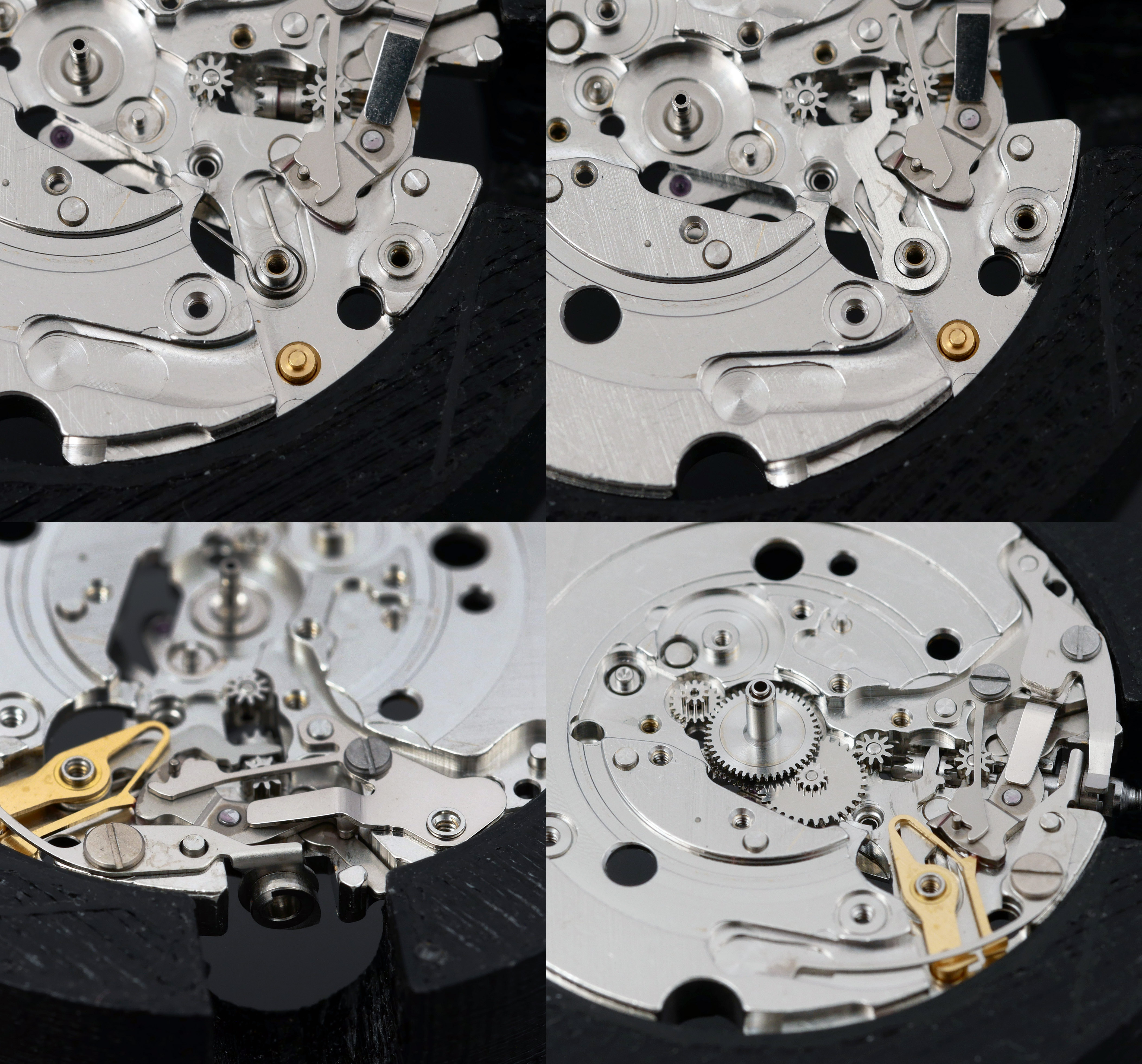 Back over to the train side and we can refit the three-wheel gear train (third, fourth and fifth) together with the seconds jumper.
 Obviously, the train wheel bridge is not in place yet, but we can see that the seconds jumper is not, at this point, in contact with the teeth of the fourth wheel. Fitting the train wheel bridge positions the three wheels correctly but there is still a gap between the tip of the jumper and the fourth wheel teeth.
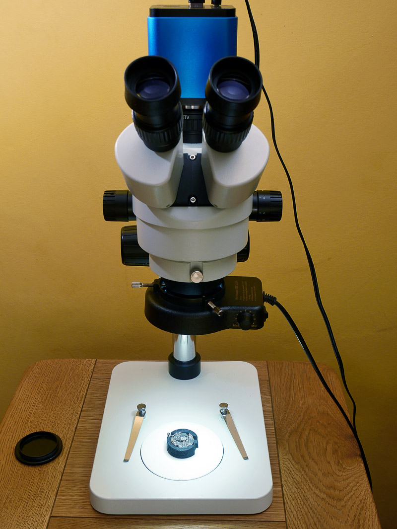
 Adjusting the seconds jumper accurately by eye is impossible. An optimist would acknowledge that to attempt to correctly align the jumper just with the aid of a loupe is at best, hit and miss. Fortunately, a little while ago, I invested in a stereo microscope that makes correct alignment, if not a doddle, then certainly massively more straightforward and certainly achievable.
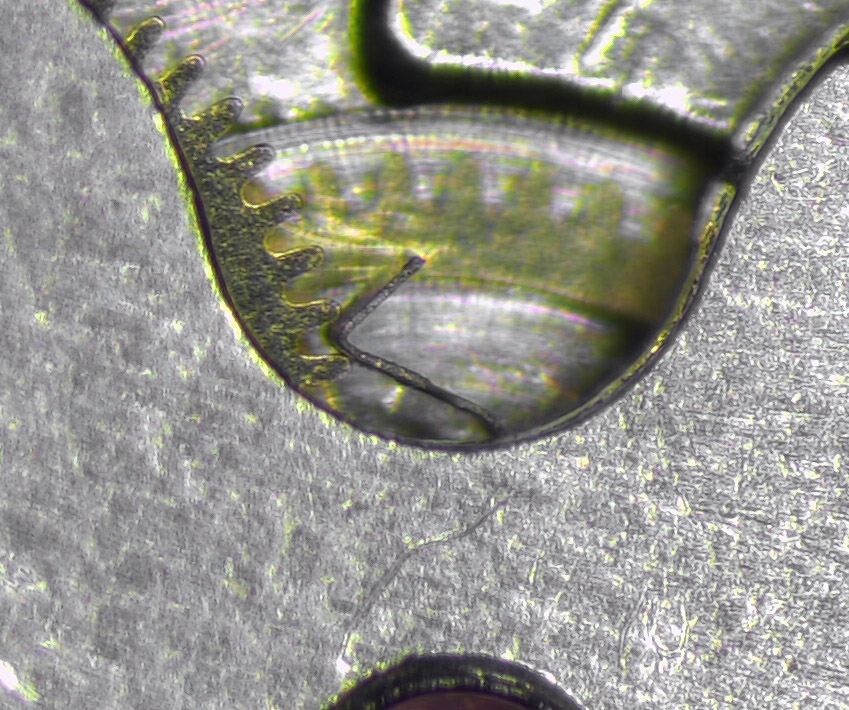
 Here is a still image taken using the microscope camera. Not quite perfect yet but almost there.
 Satisfied that the jumper is now correctly adjusted, its tip nestling between two teeth of the fourth wheel but not exerting undue force, I can fit the motor block.
 And then the coil.
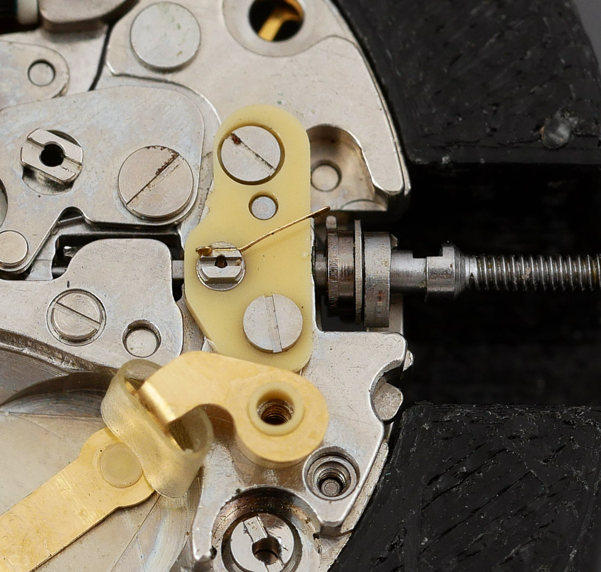
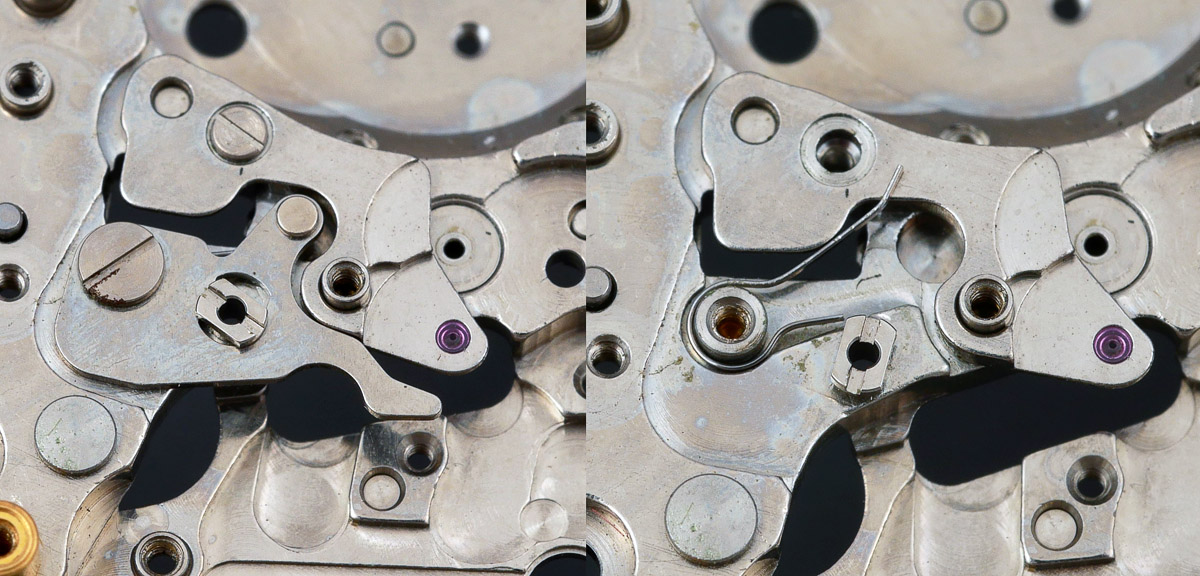
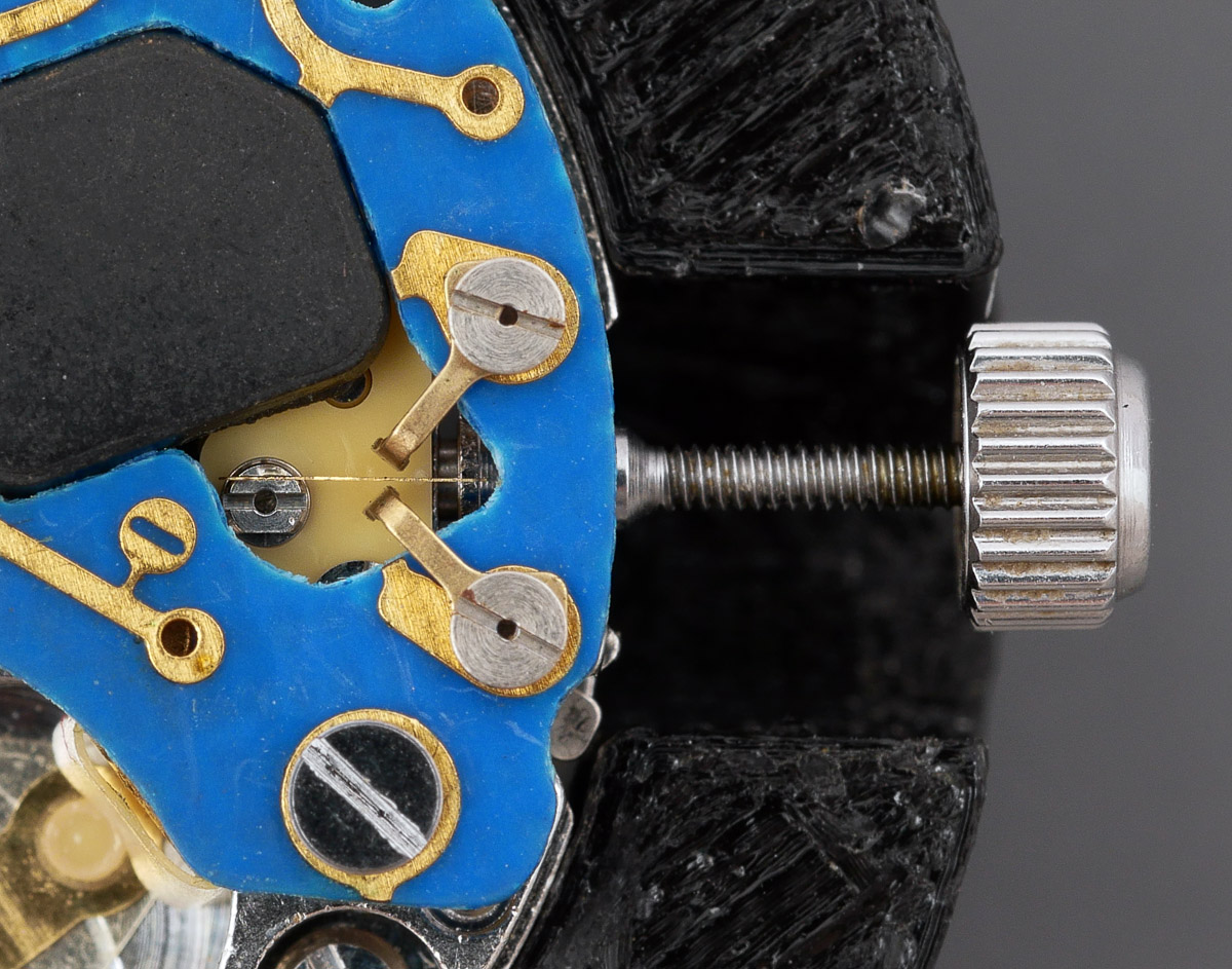
 One of the anticipated benefits of having sourced a second watch for parts was that I now had an undamaged replacement for the insulating block and tine that had been bent out of shape by a previous watchmaker. If we look closely, we can see the protuberance on the cam whose job it is to ‘pluck’ the tine as the crown is rotated either clockwise or anticlockwise when set to its inner most position.
 With the circuit board refitted to the movement, we can see that a clockwise rotation will move the tine upwards when the cam nub comes into contact with the tine, causing it to make contact momentarily with the upper arm, closing a circuit. An anticlockwise rotation will similarly cause it to make contact with the lower arm, closing a different circuit. At this point, I was still clueless about the purpose of this device, there being no English language service manual for this movement.
 Pressing on and we refit the day and date driving wheel, noting that I had previously fitted the setting wheel plate.
 We are getting perilously close to completing the deal. Next we fit, with bated breath, the date jumper and its spring.
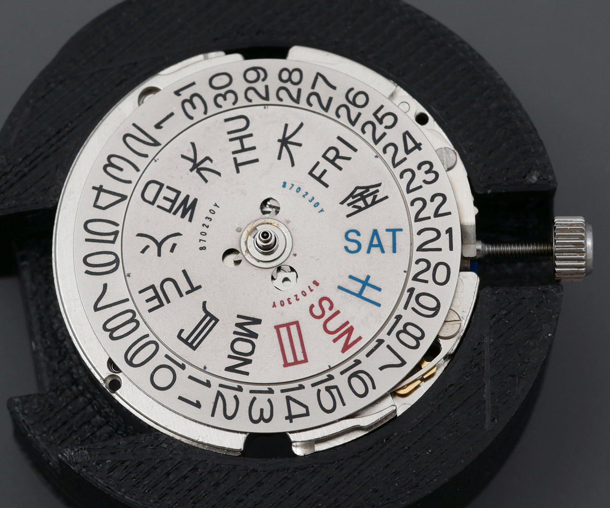
 This act marks the last point in proceedings loaded with any sort of potential for jeopardy. The cleaned date wheel seats happily, followed by the day and date jumper guards and then the cleaned day dial, topped off with its snap.
 Before fitting the dial, I take a look at its rear.
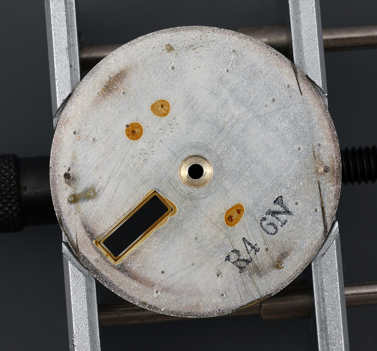 I don’t know what the code R4 GN signifies but I note the inscription made by a watchmaker, H23.3.23.SH. I interpret this to mean that the watch was serviced on the 23rd March in the 23rd year of the Heisei era. This would mean 2012 and so must be the most recent service prior to my intervention. I don’t know the significance of the letters SH but perhaps the initials of the watchmaker.
The dial spacer and dial are secured next, the feet secured by turning each of the two eccentric pins back into position.
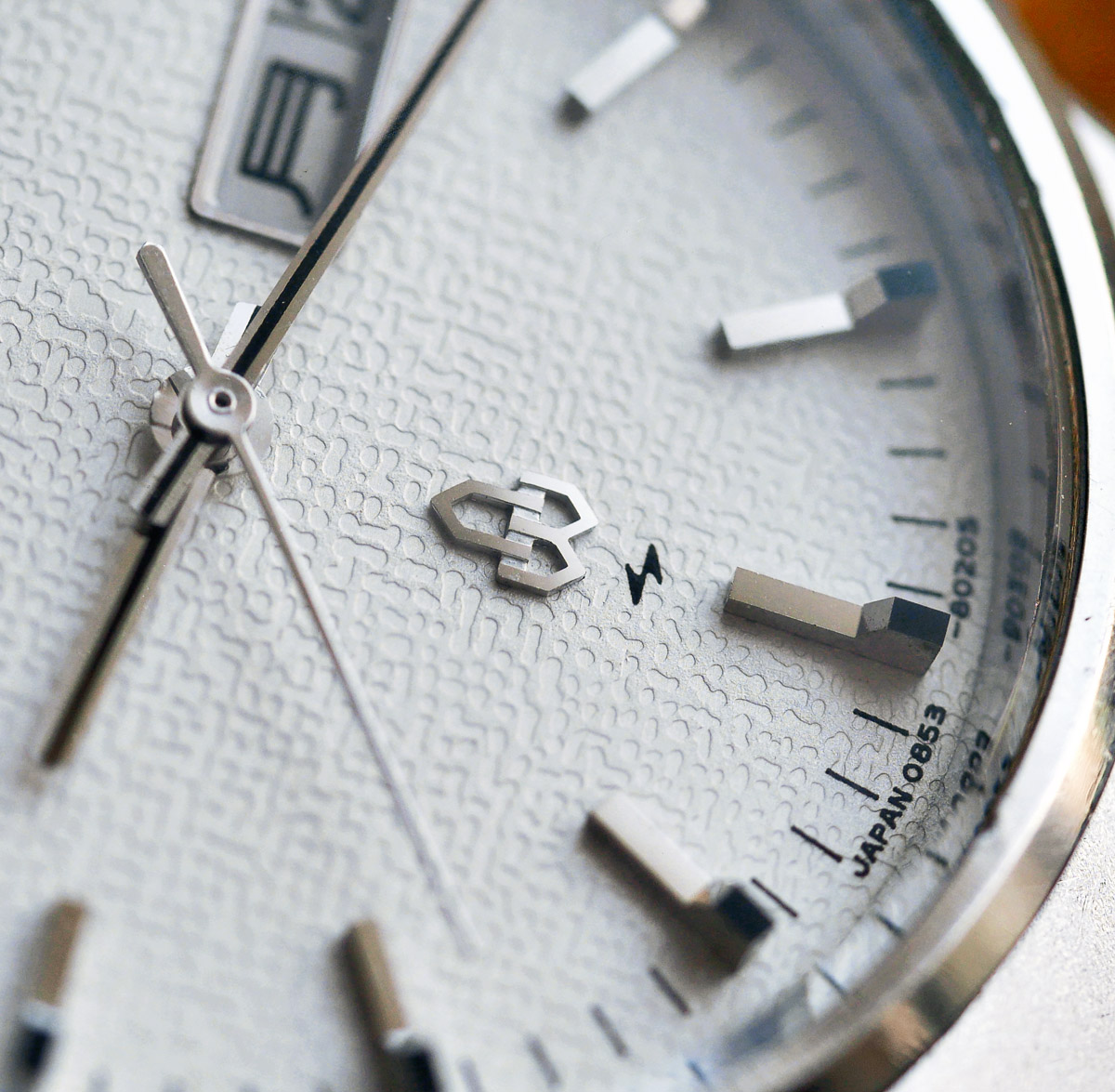
 You may be able to make out the texture of the dial surface in this photo. It has the appearance of a sheet of high-quality textured parchment. I fit the hour and minute hands next and then turn my attention back to the question of the crystal.
You will remember that we left our bezel assembly unassembled, not least because at that point, I had no crystal and no crystal gasket. Nor did I know the part number for either. After a great deal of detective work and some lateral thinking, I deduced that a likely candidate for the crystal was part number 300W59GA. Needless to say, not a whiff of a suggestion of prospect on that front and so it looked like I’d have to improvise. Similarly, with the gasket. Three understudy options suggested themselves for the crystal: 300W96GN; 300W76GN and 300W08GN. My measurements of the old rubber gasket suggested dimensions of 29.15mm ID and 30.98 OD. Armed with examples of each of these three crystals plus a generous selection of gaskets, I set about finding a combination that worked.
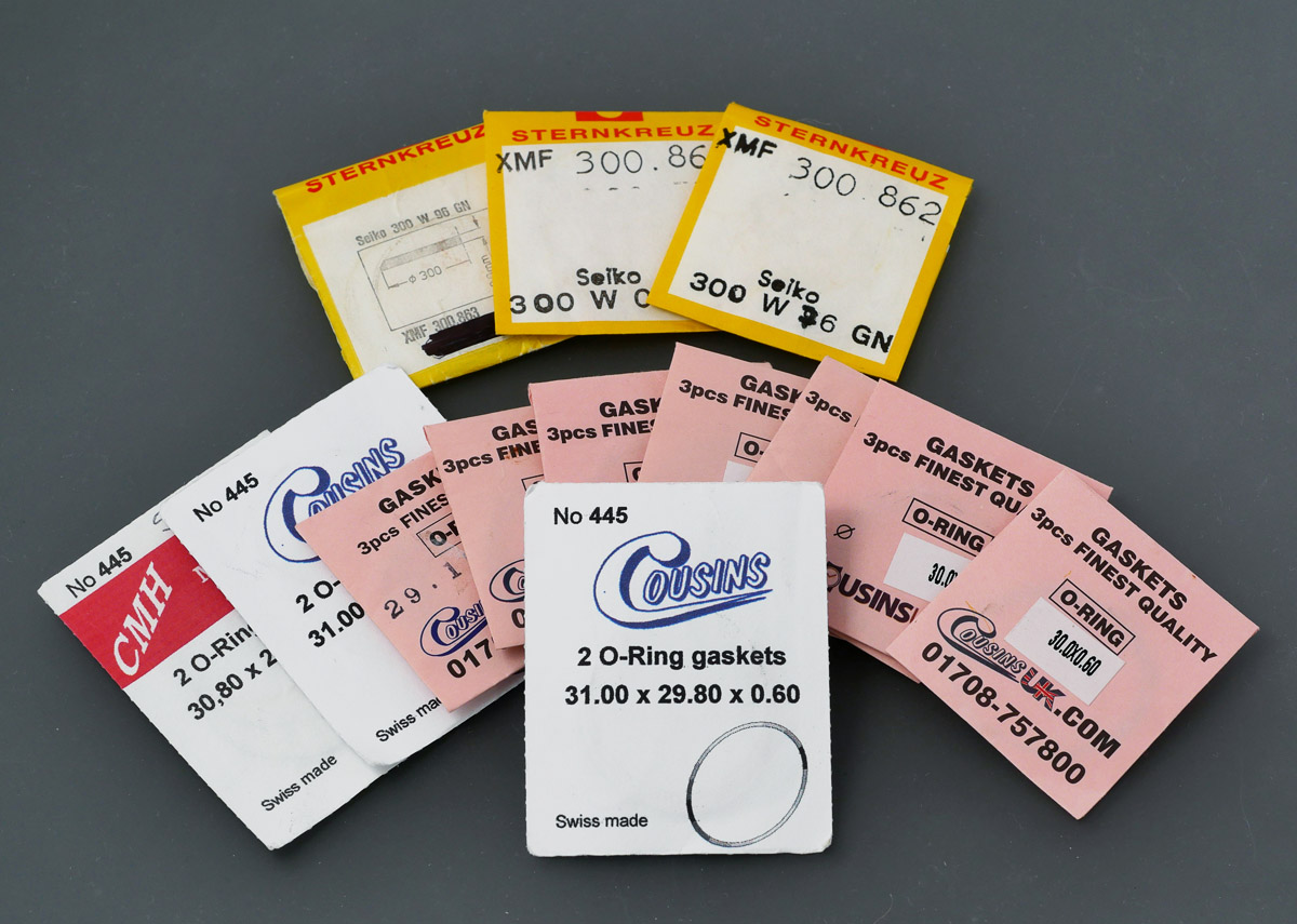 No combinations of any of the gaskets with the 300W96GN worked. Either the crystal would not seat at all or the gaskets would split. The 300W75GN would seat with 29.8 x 0.70 mm gasket but its flat sides were not deep enough to cover the whole of the gasket and it would not sit flat, popping up one side or the other and rattling about unsecured. I finally found a satisfactory combination in the 300W08GN, that had deeper verticals, with the 29.8 x 0.6 mm gasket. With that process concluded, we start by fitting the gasket into the inside groove machined into the bezel.
 The crystal presses in from the underside so that its sides rest against the gasket.
 The inner securing ring comes next, there to hold the crystal against its gasket.
 The nylon gasket is fitted back into position in the mid case.
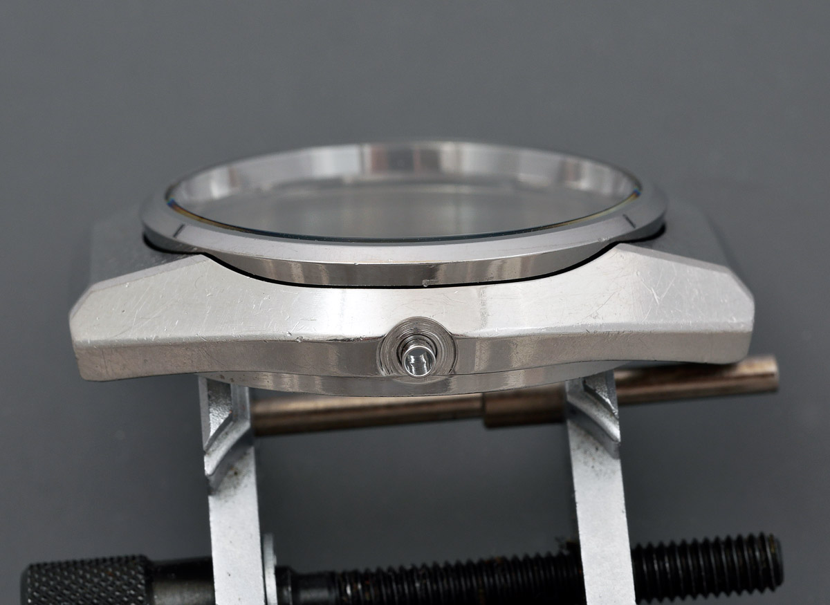
 And finally, the complete bezel, crystal and holding ring are pressed into place and the job is done.
 That was a bit of a palaver but worth the effort in the end. The case is now ready to receive the movement.
 I’d not actually tested the movement up to this point and so with a current supplied by my Horotec Flashtest, I am more than a little relieved to see the train wheels twitch (and turn) away. With a little back and forth, making sure the second jumper is working correctly, I align and fit the seconds hand. I refit the movement back into the case for the final time, select a suitable case back gasket (29.15 x 0.8 mm), and press home the case back.
 A fresh battery inserted, close up the porthole and turn her over to check all’s well.
 I am finally at the point where I can investigate the purpose of the stem cam mechanism. With the watch running, I rotated the crown clockwise until I felt a resistance that notionally prevented me from rotating the crown further. That resistance is provided by the contact of the outer cam lobe with the spring on the calendar side of the movement.
 Rotate it a little further and you hear a twang as the protuberance on the inner side of the cam plucks the tine emerging from the yellow insulating block on the train side of the movement.
 The result is a momentary pause in the travel of the seconds hand – I estimate up to about 2 seconds. Clearly this function is designed to allow re-synchronisation of the watch to a time standard if the watch has been running a little fast. Rotating the crown in the opposite direction and we encounter the same resistance followed by another twang. That has the effect of advancing the seconds hand by two seconds, thereby correcting the time if the watch has been running a little slow. I know that in this day and age, it is difficult to be impressed by old tech but nevertheless, I was both surprised and delighted to discover this thoughtful feature. You can see this in action in the short video below:
The 1975 domestic Seiko watch catalogue is filled to brimming with page after page of quartz dress watches. Once you get through the proper high-end stuff, occupying the first 23 pages, you meet the first of the more or less mainstream quartz models.
 Pages 24 through 27 contain twenty-four 38-series models, ranging from the 3883 Quartz Superior at 240,000 Yen through to the 38QT models, bottoming out at 69,000 Yen. Mixed in with those twenty-four are eight of the Daini 39-series SQ models, whose prices range from 109,000 to 98,000 Yen.
 Nine 48-series watches come next, branded as either Grand Quartz or King Quartz and ranging in price from 80,000 to 51,000 Yen. And then we come to the first eight of the 08-series watches, six of which King Quartz and two of which QT with prices ranging from 57,000 to 50,000 Yen.
 I’ll stop trying to decode the hierarchy at that point because a mix of 38-, 08- and then 09- series watches occupy the next 6 or 7 pages with 09 propping up the rear. The point of this epilogue is that the 08 series was not regarded at the time as occupying the upper echelons and of the Seiko quartz output and yet it is clear to me in having now serviced an example of the breed that this is a movement of genuine engineering excellence, a movement of substance. Yes, it is not quite as sophisticated as the 48-series and the fantastic 38, but underneath its blue collar exterior lurks more than a dash of a blue blood.

That was a pleasure Martin, really enjoyable. Seeing the subject of this post had was a thrill as I am currently waiting for the delivery of a 9443 7000, I have been following it’s progress with anticipation but it is currently bottlenecked at Bristol customs/excise.
Your description of removing the bezel and crystal was informative and will save me a lot of frustration, not a straightforward job and info regarding substitute parts is really helpful. It’s a job I certainly will not be undertaking as I think I would lack the talent for even the most basic fettling.
Where does the 9443 7000 fit in relation to models discussed in this post?
Thanks again Martin for “joining the dots”
Many thanks Gilmour. The 9443 is a later twin quartz calibre, released I think in 1980. The two crystal oscillators operating at different frequencies.
Very interesting, I own a King Quartz 5856-8020 which must be in many ways almost identical in design, same bracelet, same case shape, same indices, it even has the 2 second adjustment feature.
Have you ever tried employing a strong magnet when looking for small fiddly bits of metal? Always seems to do the trick for me.
The trouble with springs is they can launch themselves a long way from the scene of the crime. I’ve not tried the magnet approach but may give it a try in the future. This one though I think is properly lost!
Another approach would be to use an empty bagless vacuum, to use it over a wide area and then to run a magnet through all the stuff that’s been picked up.
I like this as a suggestion but I still need to buy a sizable magnet!
Nice! I have a 5856 on the way and I was wondering if it had the time correction feature like the 08xx/09xx, but I couldn’t find any information about it. So, when you turn the crown far enough, you feel a click and it jumps one sec (or pause if turning the opposite way)?
Thanks!
I don’t know if you’ve looked at the accompanying YouTube videos (there are two) but they both show the feature in operation. As far as I know, the 5856 does not have the same feature but I’ve neither handled nor worked on an example of that movement family.
Hello Martin, thanks for getting back to me. I received my King Quartz 5856 today and I can confirm, it does have the time correction feature! Just like this 0853. Pretty happy about that! Cheers,
Jonathan
hello, i have the exact model. I tried to remove the case ring, but i cannot. what tool did you used? do you pull it out or slide? can you show me the procedure?
thanks in advance 🙂
as you can see here it’s rusty : https://d.pr/i/aETfkn i tried to use a tool but more i try more i damage the ring
another photo : https://d.pr/i/M8JcS3
and last problem : a sping bar was so rusty it has instantly broken and is stuck in the hole, have you got a tip for this? https://d.pr/i/nwumSE
thanks
None of your photos is showing so I can’t offer more advice than in my last reply I’m afraid. With rusty spring bars, probably the only option is to drill out the broken end. Not ideal and you have to proceed with caution!
The case ring should just drop in but if its rusted in then you’ll just have to find a way to jiggle it gently out.
Great report, brilliant photos and – being a watch fettler myself – I absolutely enjoy your writing style and the generosity in admitting what can go wrong. In my experience you will find this spring by accident (when searching for the next lost part) at the very point in time you don’t need it anymore. I found out the same bezel removal method for myself when dealing with early Seiko Type II (e.g. 0903) – a lot of them have these double bezels. To get more grip for a bezel sitting very tight or if the press disc is not fitting 100%, I insert the inlay of an armored acrylic watch glass which i have cut on one side to form something like a circlip (i hope that description is understandable, battling a bit to find the proper english words).
Thank you Georg, I really appreciate both the feedback and the useful tip. Martin
And yes, I am sure you are right about the lost spring. For the moment it is still lost but I find old lost parts on a regular basis so am confident it will show up sooner or later!
… to continue from yesterdays writing:
As I also own some 0853s, I tried the second adjustment feature and found it working – nice to have learned about this !
BTW there have been different approaches to this adjustment, notably Citizen 8600 and Ricoh 580 have used an extra button that one would press when listening to the “hour” beep in the radio and which would halt the movement for up to 30 excess seconds when the watch was in advance or would rapidly move forward the second hand to the 12 o’clock marking when the watch was behind. The Citizen 8600 movement would fill the waiting time with a blinking LED located at the 12 o’clock index (this LED normally just blinks once when the second hand hits the 12) – a very nice overengineering feature,
that on the downside introduces the need to initially sync the second position with the LED somehow …
I am wondering a bit, why the early quartz watches have this second jumper (can also be seen with Citizens and Ricohs) and why it was given up later.
First, I thought it has something to do with the 6-pole rotor of the 3803 stepping motor and would not be necessary with the 2-pole design used later througout (actually I am not sure what the design of the 0853 rotor is?).
But maybe – with the high price levels for these watches – the visual indication of precision with the second hand hitting the index marker spot-on was important and the second jumper allows some fine tuning without having to refit the second hand ?
Or is it meant to remove the wiggling of the second hand resulting from some excess torque ?
The reason why it was left away later is much more apparent to me, as the proper adjustment is quite cumbersome and there is a risk for this device causing the movement to malfunction. Or one can lose the jewel mounted at the end of the spring …
I like the approach taken to the seconds hand adjustment with the 0903 very much –
pulling the crown will fix the 2-pole stepping motor rotor in an “even seconds” position, making it very easy to mount the seconds hand properly.
Best regards, Georg
Excellent. I have a 1978 5856 5010. Is that similar to the 0856? Mine has the stepper motor. Thanks Nigel.
I’ve not worked on a 5856 but photos of that movement suggest it is quite a different design in terms of layout.
Thanks for another wonderful and informative essay, Martin. I mostly collect 70’s Seiko quartz watches in the 3802 and 3803 series. I have seen only one other reference to the +/- second adjustment, on the crown of the 5856–I didn’t know the 0853 had it too. it seems to be a well-kept secret.
It seems to me that the Daini cases are often complex. I very frequently notice some moisture damage around the perimeter of the dials of those offered for sale. I’m guessing that the gaskets are gone, and not easily replaced.
Thanks again. I enjoy your series very much.
Brian Donnell
I’m glad you enjoyed this one Brian. Daini often seemed to be the arm which innovated more than the other, sometimes at the expense of over-complicated designs but always to be admired.
I am currently in an endless mind melting search for a battery door. There seem to be so many variation but not the one I need(I have a KQ 8010 case no battery door). I’m temped to buy one of those bags of battery doors people sell on ebay 😅 I’m wondering if some have different numbers but sill fit different case numbers, similar to how seiko crystal and mainsprings go – different serial but will fit different models.
Hi Wolfgang, my guess is that many/most/all of the 0853 models will use the same battery hatch and my strategy would probably be to buy as cheap an example of another 0853 as a parts donor as I can find. You might find it cheaper to buy a complete watch than to find a separate battery hatch. The 0852 variations should work too. Good luck!
ha! very good call. Either buck up 30$ for just the battery hatch or 44$ for a very ugly, yet complete KQ only a year prior to mine. Thanks again Martin. Your blog serves us all very well.
Question
What is the battery replacement reference please
I believe it is SR43SW (301).
Hi do you rate the Seiko King Quartz 5856-8030 8Jewels movement?
Hi Phil, I’ve not worked on one yet so not formed an opinion. Bit I expect one will pass through at some point 🙂
Love your work on that quartz movement.
Thank you for posting.
Lasse, Norway.
Thank you for your comment Lasse. I appreciate it!
Hi Martin,
We’re you ever able to source a service manual for this movement? I am searching for the correct part number for the circuit block for the 0853, however countless internet searches have yielded little in the way of results.
Thanks,
Kevin
Hi Kevin,
No I used the 0843 manual together with two pages from a Japanese language version of the technical manual. I can’t remember where I found the latter but it doesn’t have part numbers in any case.
Hello Martin, I love your blog and I have been constantly following it since when I discovered it.
The other day, by chance, I was going through the technical manual of cal. 08 and I could not find any information about its thermocompensation method. Can you shed some light, please, and maybe point at it in your teardown?
Thank you very much and keep up with the good work.
Best,
Federico
Hi Federico,
Seiko refer to special condenser for temperature compensation in a number of different calibres from this era, and if you look at p.9 of the 3003 (0843A) service manual, you will see the temperature compensating condenser indicated. I have not found any description though in any technical manual of how this actually works!
Shoot! How did I miss it?! That’s one of the beauty of Seiko, great features, tight implementation and yet it has rarely been loud about them. Thank you so much, Martin
Best,
F
Hi,
Does anyone know what KQ model does my bracelet (XQB 500) fit on?
thank you
I am struggling to find a battery hatch gasket that fits properly. Could you let me know witch size you found works the best. Thanks.
Hi Mike, I don’t have a record of the size to hand but I’ll see if I can figure it out and will post here if I do.
I’ve restored more than half a dozen early quartz and I believe 48xx(A variant) and 0853 use the same battery hatch gasket – I’ve landed on 13.50 x 14.50 x 0.50mm ISO swiss. A user on Wristsushi suggests 13.20 x 14.40 x 0.50mm, ISO Swiss but for the 48xx. hope that helps! These are some of the best quality quarts watches, even by today’s standards.
Thanks for that Wolfgang. Much appreciated.
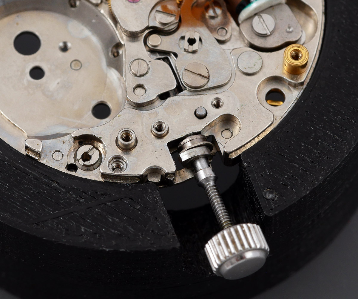
Hi Martin was hoping you can advise on how to remove the stem from the 0853 movement.
Regards
There is a lever to the side of the crown with a little semi-circular tab at its end. You can see it in several of the photos in the article. You just depress it and withdraw the crown.